
Table of Contents
ToggleHi-Tech Screw Barrel repairs screws and barrels in-house in Ahmedabad for manufacturers across India.
- Typical turnaround: 1–3 weeks (depending on scope)
- Warranty: 6 months on all repair work
Introduction — The Hidden Cost of Ignoring Wear
Somewhere on your production floor right now, a screw and barrel are quietly losing you money. Not dramatically — no bang, no fire, no shutdown that forces anyone to pay attention. The loss shows up in small, easy-to-explain-away ways: output that’s a little lower than it used to be, an amperage reading that creeps up month over month, a scrap rate that hovers just high enough to be annoying but not high enough to trigger an investigation, and a maintenance team that’s quietly gotten used to running the line “a little hotter” or “a little slower” to keep parts in spec. This is what worn screw and barrel components look like in the real world — and it’s the exact problem we solve in our repair shop in Ahmedabad every week.
This is what worn screw and barrel components look like in the real world. They rarely fail catastrophically without warning. They degrade gradually, and because the degradation is gradual, plants adapt to it rather than fixing it. Operators nudge temperature setpoints. Process engineers adjust screw speed. Quality technicians tighten inspection criteria. Everyone works around the problem instead of addressing the root cause, and the cost of that workaround compounds daily in the form of wasted energy, wasted material, wasted cycle time, and a growing risk that the part will fail at the worst possible moment — usually during a large production run against a tight customer deadline.
The purpose of this guide is to give you a complete, practical understanding of screw and barrel repair: why wear happens, how to recognize it before it becomes a crisis, how the repair process actually works step by step, what a quality repair should look like, and when repair is — and is not — the right answer. This is written for plant maintenance managers, process engineers, procurement teams, and plant owners who need to make an informed decision rather than simply reacting to symptoms.
Repair and rebuilding are, in the large majority of cases, dramatically more cost-effective than replacement. A well-executed repair does more than patch a worn part — done properly, with modern hardfacing alloys and premium barrel liner materials, a rebuilt screw or relined barrel can outperform the original component’s wear life. That is not a marketing claim; it is a straightforward consequence of the fact that repair shops can apply harder, more wear-resistant surface treatments than what many components originally shipped with from the factory. Understanding when and how to take advantage of that opportunity is the core subject of this guide.
We will walk through the anatomy of the plasticating unit, the physics of why wear occurs, how to diagnose and measure it accurately, the detailed mechanics of the repair process for both screws and barrels, how to evaluate whether a repair shop has done the job correctly, what repair should reasonably cost and how long it should take, and how to build a maintenance program that extends the life of your equipment going forward. By the end, you should be equipped to make repair decisions with the same confidence as an experienced plant engineer who has been through this process dozens of times.
Anatomy of a Screw & Barrel System
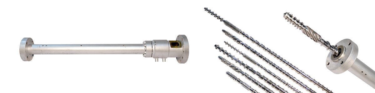
Before diagnosing or repairing wear, it helps to have a precise shared vocabulary for the components involved. A screw and barrel assembly — whether on an extruder or an injection molding machine — is often described casually as “the screw” or “the barrel,” but each is actually a system of distinct functional zones and sub-components, each of which wears differently and requires different repair approaches.
The Barrel
The barrel is the stationary cylindrical housing inside which the screw rotates (and, in injection molding, also reciprocates axially). Its key structural elements include:
• The bore — the precision-machined internal cylindrical surface against which the screw’s flight tips ride. This is the single most critical wear surface in the entire system, because the clearance between the flight OD and the bore ID directly governs how much material can leak backward past the flights (more on this in Part 2).
• The liner — many barrels are not solid through-hardened steel from bore to outer wall. Instead, they use a bimetallic construction: a base structural steel body with a separate wear-resistant liner metallurgically bonded (typically via centrifugal casting) to the bore surface. The liner is what actually contacts the plastic and the screw; the base steel provides structural strength and heat transfer.
• Heating/cooling zones — external band heaters and, in some designs, internal cooling channels regulate barrel temperature along its length. These aren’t a wear item in the traditional mechanical sense but matter to repair planning because barrel work often requires removing and later reinstalling heater bands.
• The feed throat — the opening near the rear of the barrel where raw material (pellets, powder, or regrind) drops in from the hopper. This area experiences its own distinct wear pattern from the impact and abrasion of incoming solid material.
• The discharge end / nozzle interface (injection molding) or die adapter interface (extrusion) — the front of the barrel where molten material exits toward the mold or die. This zone often runs hottest and, in injection molding, experiences the highest instantaneous pressures.
• End caps and flanges — the barrel’s mounting interfaces to the rest of the machine.
The Screw
The screw rotates within the barrel bore and is responsible for conveying, compressing, melting, and metering the plastic. Its zones and components include:
• The root — the solid central shaft of the screw, whose diameter typically increases from the feed end to the metering end. This creates the compression that helps melt the material.
• The flight — the helical ridge wound around the root. The flight’s outer diameter is machined to run with a small, precise clearance from the barrel bore. Flight tips are the primary wear surface on the screw side, in direct analogy to the barrel bore.
• Feed zone — the section (usually with the deepest channel depth and constant root diameter) where solid pellets are conveyed forward and begin to soften.
• Transition (compression) zone — where channel depth decreases as root diameter increases, generating the compression that promotes melting and eliminates air pockets.
• Metering zone — the final section, with shallow, constant channel depth, where the screw homogenizes the melt and generates the consistent pressure needed to push material through the die or into the mold.
• Mixing sections — many modern screw designs incorporate specialized mixing elements (pins, Maddock/Union Carbide mixers, pineapple mixers, barrier flights) to improve melt homogeneity, particularly with masterbatch color, additive dispersion, or difficult-to-melt resins.
• The screw tip / non-return valve assembly (injection molding specific) — a check ring and seat assembly at the front of the screw that allows melt to flow forward during injection but prevents backflow during screw recovery. This assembly experiences some of the most severe wear in the entire system due to constant opening/closing cycling under pressure.
• The drive end — the rear of the screw, which couples to the machine’s drive train (gearbox, thrust bearing housing).
Why This Anatomy Matters for Repair
Every one of these components wears through a different mechanism and at a different rate, and a competent repair provider treats them as distinct diagnostic and repair problems rather than treating “the screw” or “the barrel” as a single monolithic part to be inspected once and repaired uniformly. A screw might have severe flight wear in the feed zone but a perfectly serviceable metering zone. A barrel might be fine along most of its length but badly scored near the feed throat from an incident of metal contamination. Understanding zone-by-zone anatomy is what allows a repair shop to target work precisely — repairing only what needs repair — which is part of why professional rebuilding is so much less expensive than wholesale replacement.
How Melting & Conveying Actually Work
To understand wear, you first need to understand what the screw and barrel are mechanically doing to the plastic as it passes through, because wear is largely a byproduct of the forces involved in that process.
Solids Conveying
At the feed zone, plastic enters as solid pellets, powder, or regrind flake. The screw’s rotation, combined with friction between the pellets and the barrel wall (which should be higher than the friction between pellets and the screw root), drags the material forward in a corkscrew motion. This is a friction-dependent, not melt-dependent, transport mechanism — it’s essentially a solid plug being dragged along the barrel wall by the screw’s rotation, similar in principle to how a nut moves along a threaded bolt when the nut is prevented from rotating with the bolt.
This has a direct wear implication: the feed zone flight tips experience continuous abrasive contact with solid, often abrasive pellets (especially glass-filled or mineral-filled compounds) at a point where there is no lubricating melt film yet present. This is one reason feed-zone wear is frequently the earliest and most severe wear pattern observed on a screw.
Melting Mechanism
As the solid bed moves into the transition zone, heat from the barrel (conduction) and from viscous shear (frictional heat generated as material is worked between the screw and barrel) begins melting a thin film against the hot barrel wall. This melt film is then scraped off and accumulated into a melt pool at the leading edge of each flight by the wiping action of the flight itself. Over the length of the transition zone, this melt pool grows while the remaining solid bed shrinks, until — ideally — melting is complete before the material reaches the metering zone.
The efficiency of this melting mechanism depends heavily on maintaining the correct, tight radial clearance between the flight tip and the barrel bore. That clearance is precisely what wear destroys over time.
Pumping & Metering
In the metering zone, the screw acts as a positive-ish displacement pump (positive displacement in an idealized model, though real output is always somewhat less than theoretical due to leakage flow — which we’ll return to shortly). Consistent channel geometry here is what gives you a consistent, predictable output rate and consistent melt pressure delivered to the die or mold.
Why Clearance Is the Single Most Important Wear Variable
Every one of these three functions — solids conveying, melting, and metering — depends on the flight tip maintaining a tight, consistent radial clearance against the barrel bore. When that clearance grows because of wear, material begins to leak backward over the flight tips instead of being pushed forward as intended. This leakage flow is the central mechanical consequence of wear, and it’s worth understanding in detail because virtually every symptom of a worn screw and barrel system traces back to it.
Types of Screws & Barrels Covered in This Guide
Screw and barrel repair principles apply broadly across plastics processing equipment, though the specific geometry and failure patterns vary somewhat by machine type. This guide covers:
• Single-screw extruders — used for pipe, profile, sheet, blown film, cast film, wire and cable coating, and compounding lines.
• Injection molding screws and barrels — reciprocating screw designs used across all injection molding applications, from thin-wall packaging to heavy industrial parts.
• Twin-screw extruders (compounding and some processing lines) — while twin-screw elements have their own specialized repair considerations (particularly around segmented screw elements and barrel liner sections), the wear mechanisms and general repair philosophy overlap significantly with single-screw systems and are referenced throughout.
• Barrier screws and specialty mixing screws — advanced screw geometries with separate solid and melt channels, common in high-output extrusion.
• Vented barrels — used in extrusion applications requiring volatile removal (moisture, monomer, or other off-gassing), which have an additional vent opening that introduces its own wear and contamination considerations.
• Blow molding screws and barrels — mechanically similar to extrusion screws but typically designed around narrower material windows for specific resin types.
While the finer engineering details differ across these categories, the fundamentals of wear diagnosis, measurement, and repair described in this guide apply consistently across all of them.
Industries & Applications Affected by Wear
Screw and barrel wear is a universal issue across virtually every plastics processing sector, though the wear profile differs by application:
• Packaging — high-speed, high-volume lines running commodity resins (PE, PP, PET) often see wear driven primarily by sheer cycle count and thermal cycling rather than abrasive fillers, though recycled content is increasingly a factor as sustainability mandates push more regrind and post-consumer resin into packaging lines.
• Pipe, profile, and sheet extrusion — long, continuous runs with high throughput demands mean that even small percentage losses in output translate into large absolute losses in production capacity. These lines often run PVC, which introduces corrosive wear alongside abrasive wear.
• Wire and cable — coating applications frequently run flame-retardant compounds loaded with mineral fillers (aluminum trihydrate, magnesium hydroxide) that are highly abrasive.
• Blow molding — screws here often see less abrasive wear but more thermal-cycling-related fatigue given the frequently intermittent nature of the process.
• Compounding — twin-screw compounding lines that introduce glass fiber, carbon fiber, mineral fillers, or reinforcing additives at high loadings are among the most demanding applications for screw and barrel wear resistance, often requiring the most aggressive hardfacing and liner solutions available.
• Recycling and reprocessing — lines dedicated to processing post-consumer or post-industrial regrind see accelerated wear from contamination (metal fragments, sand, dirt) that is far less controlled than virgin resin feedstock.
Regardless of which of these categories describes your operation, the underlying repair principles in this guide apply; only the frequency of required maintenance and the specific hardfacing/liner selection will differ.
Why Repair Should Be the First Consideration, Not Replacement
It’s worth stating plainly, at the outset of this guide, the central philosophy behind everything that follows: in the significant majority of wear situations, repair and rebuilding is a better decision than full replacement — on cost, on lead time, and often on resulting performance.
There are three reasons for this:
First, cost. A full repair or rebuild — including flight rebuilding, hardfacing, and barrel relining — typically costs a fraction of the price of a new screw and barrel set, particularly for larger diameters where raw material and machining costs for a brand-new component scale up significantly.
Second, lead time. New screw and barrel manufacturing, especially for custom or large-diameter equipment, can involve lead times of many weeks once you account for raw material procurement, rough machining, heat treatment, finish machining, and quality inspection. A repair, by contrast, works with an existing core (the root steel of the screw, the structural body of the barrel) and typically turns around in one to three weeks, sometimes faster with expedited service.
Third, and perhaps most counterintuitively, performance. Because repair shops can apply hardfacing alloys and barrel liner materials that are harder and more wear-resistant than many original factory finishes, a properly rebuilt screw or relined barrel can actually outlast the original component. This is a genuinely important point that’s easy to overlook: repair isn’t just “getting back to where you started” — it’s often an opportunity to upgrade wear resistance beyond the original design.
None of this means replacement is never the right call — Part 6 of this guide covers exactly when repair limits are reached and replacement becomes unavoidable, and if you’re at that point already, our companion guide on screw barrel replacement covers that process in full depth. But as a starting philosophy: default to investigating repair first, and treat replacement as the fallback rather than the default. ## 7. Root Causes of Screw & Barrel Wear
Wear is never a single-cause phenomenon. In almost every real-world case, several of the following mechanisms are operating simultaneously, and part of an accurate diagnosis is figuring out which mechanism is dominant so the repair (and any process changes) can be targeted correctly.
Abrasive Fillers
Glass fiber, mineral fillers such as talc and calcium carbonate, flame-retardant packages like aluminum trihydrate and magnesium hydroxide, and various reinforcing additives are, mechanically speaking, hard particulate matter suspended in a softer polymer matrix. As this compound is conveyed and sheared between the screw flight and the barrel bore, these hard particles act like a slow-motion grinding compound, continuously eroding both surfaces at a rate roughly proportional to filler hardness, filler loading percentage, particle shape (angular particles are more abrasive than rounded ones), and the shear intensity in the zone where they’re concentrated.
Glass-fiber-reinforced nylon and polypropylene compounds are among the most notoriously abrasive materials processed in plastics manufacturing, and processors running these resins at high volume should expect wear rates significantly higher than those running unfilled commodity resins — often by a factor of three to five times or more, depending on fiber loading and length.
Corrosive Resins
Some materials attack metal surfaces chemically rather than (or in addition to) mechanically. PVC is the most common example: at processing temperatures, PVC releases small amounts of hydrochloric acid as it degrades thermally, and this acid attacks unprotected steel surfaces, particularly in areas where residence time is longer than ideal (dead spots, sharp corners) or where temperature excursions occur. Certain flame retardants and some specialty engineering resins with halogenated additives present similar corrosive challenges. Acetal (POM) resins can also release formaldehyde under certain degradation conditions with its own corrosive characteristics.
Corrosive wear differs from abrasive wear in an important way: it tends to produce pitting and surface roughening rather than smooth, even material loss, and pitted surfaces then accelerate abrasive wear because they create additional friction points and turbulence in the melt flow — meaning corrosive and abrasive wear mechanisms often compound each other rather than acting independently.
Regrind & Recycled Material Contamination
As sustainability initiatives push more processors toward incorporating regrind, post-industrial scrap, or post-consumer recycled resin into their material streams, contamination-driven wear has become an increasingly significant factor. Regrind streams can carry small metal fragments (from grinder blades or upstream metal contamination in the waste stream), sand, dirt, and other hard foreign material that virgin resin simply doesn’t contain. Even a small percentage of contaminated regrind blended into an otherwise clean material stream can introduce localized, severe wear or even sudden, dramatic damage if a large enough foreign object passes through the feed throat.
Radial Clearance & Leakage Flow
This is less a root cause in the traditional sense and more the mechanical feedback loop that turns “some early wear” into “severe wear” over time. As explained in Section 3.4, wear increases the radial clearance between the flight tip and barrel bore. Increased clearance allows more melt to leak backward over the flight tip rather than being conveyed forward as intended. This leakage flow is subjected to intense shear as it’s forced through the narrow leakage gap, generating localized frictional heat and additional turbulence. That additional heat and turbulence, combined with the simple fact that more melt is now passing directly over and scrubbing against the worn tip surface, accelerates the wear rate further. This is why wear, left unaddressed, doesn’t progress linearly — it accelerates over time, and a screw that took years to reach mild wear can go from mild to severe in a much shorter span once this feedback loop takes hold.
Misalignment & Thrust Bearing Wear
The screw must rotate perfectly concentrically within the barrel bore. Any misalignment — whether from worn thrust bearings in the drive train, a bent screw root, worn drive train bushings, or improper reassembly after a previous repair — causes the screw to ride off-center within the barrel, creating uneven, one-sided wear patterns rather than the even, circumferential wear you’d expect from normal operation. This is important diagnostically: uneven or one-sided wear patterns on a barrel bore or screw flight are a strong signal that a mechanical alignment issue exists somewhere in the drive train, separate from and in addition to routine material-driven wear, and repairing the screw or barrel alone without addressing the underlying alignment problem will simply lead to rapid recurrence of the same wear pattern.
Overheating & Thermal Degradation
Excessive shear heat (often itself a symptom of clearance wear, as described above) or improperly set barrel temperature profiles can cause localized overheating that degrades both the polymer and, over time, the metallurgy of hardfaced surfaces. Some hardfacing alloys have upper temperature limits beyond which their hardness and wear resistance begin to degrade; chronic overheating in a particular zone can quietly undermine a hardfacing treatment that would otherwise have performed well.
Foreign Debris & Metal Contamination
Beyond the regrind-contamination scenario already discussed, foreign debris can also enter a system through maintenance mistakes (a dropped tool or fastener), upstream process failures (a broken screen pack sending mesh fragments downstream), or occasionally through failures in earlier stages of the same machine (a fractured piece of a wear part breaking off and traveling further down the barrel). Metal-on-metal contact between a foreign object and the screw or barrel bore typically produces sudden, severe, localized damage — gouges, scoring, or dents — that looks visually distinct from the smooth, gradual wear pattern of abrasive or corrosive mechanisms, and this distinction is diagnostically useful.
The Physics of Clearance-Driven Wear
It’s worth dwelling further on the feedback loop introduced in Section 7.4, because understanding it changes how you think about maintenance timing.
The Compounding Nature of Clearance Wear
Picture radial clearance as starting at a design value — often somewhere in the range of a few thousandths of an inch per inch of screw diameter for many designs, though the exact figure depends heavily on screw diameter, design, and application. At this design clearance, leakage flow is minimal, and the vast majority of material moving through the metering zone is being positively conveyed forward as intended.
As wear increases this clearance, a larger fraction of the throughput leaks backward through the growing gap. This leaked material typically experiences extremely high, localized shear rates as it is forced through a narrow gap under pressure — shear rates can be many multiples higher in the leakage gap than in the main channel flow. High shear generates heat through viscous dissipation. That localized heat further reduces the melt viscosity right at the wear surface, which — counterintuitively — can increase leakage flow rate further (lower viscosity melt leaks more easily), and the additional heat exposure and turbulence increases the abrasive/erosive action against the flight tip and the barrel bore in that exact location.
The net effect: once clearance grows past a certain threshold, the rate of wear at that location tends to increase, not stay constant. This is why maintenance professionals frequently talk about “wear accelerating” rather than progressing steadily, and it’s the core technical justification for measuring and tracking clearance over time rather than waiting for gross symptoms to appear before investigating.
Relationship Between Clearance, Output, and Melt Quality
The practical consequences of this physics are direct and measurable:
• Output drops because a growing share of theoretical throughput is being recirculated backward instead of delivered forward.
• Energy consumption per pound of output rises because the same (or more) drive horsepower is now being spent shearing recirculating melt rather than doing useful conveying work, and because operators often compensate for output loss by increasing screw speed, which further increases energy draw.
• Melt temperature becomes less stable and often trends upward because of the additional localized shear heating in the leakage zone, and this instability shows up as inconsistent part quality, surface defects, or dimensional variation.
• Melt homogeneity degrades, particularly for color or additive dispersion, because the leakage flow disrupts the orderly, predictable flow pattern that a well-designed screw geometry is meant to produce.
Warning Signs & Symptoms Checklist
Because wear rarely announces itself with an obvious single event, it’s useful to have a structured checklist of the indirect signals that, together, paint a clear picture. No single symptom below is conclusive on its own — each can have other causes — but a cluster of several of these appearing together, especially if they’re trending in the wrong direction over weeks or months, is a strong signal that screw and/or barrel wear is the underlying driver.
Output / Throughput Decline
The most direct symptom: at a given, unchanged screw speed and temperature profile, the line is producing less pounds-per-hour (extrusion) or requiring more recovery time to reach shot weight (injection molding) than it did previously. Because this decline is usually gradual, it’s often only noticed when someone compares current production logs to historical records from months or years earlier — which is exactly why maintaining production trend data over time is so valuable.
Rising Energy Consumption
Motor amperage draw, particularly relative to output achieved, tends to climb as clearance-driven leakage flow forces the drive system to do more shearing work per pound of usable output produced. A rising kWh-per-pound trend, even a slow one, is a meaningful early indicator worth tracking.
Melt Temperature Instability
Increased localized shear heating from leakage flow, described in Section 8, tends to make melt temperature both higher on average and less stable shot-to-shot or over time, even when barrel heater setpoints haven’t changed.
Scrap / Reject Rate Increases
As melt quality and consistency degrade, downstream part quality suffers — surface defects, dimensional variation, color streaking, incomplete fills, or voids can all trace back to inconsistent melt delivery from a worn plasticating unit. An uptick in rejects that quality teams can’t attribute to raw material, tooling, or mold issues is worth investigating from the screw and barrel angle.
Erratic Cushion (Injection Molding Specific)
In injection molding, the “cushion” — the small amount of melt intentionally left in front of the screw at the end of injection — should be highly repeatable shot to shot. Worn check rings/non-return valves (see Section 20) or excessive barrel-to-screw clearance can cause cushion to vary unpredictably, or in severe cases, the machine may struggle to hold any cushion at all, a serious symptom that typically indicates check ring or valve seat wear has progressed significantly.
Cycle Time Creep
If recovery time (injection molding) or the time needed to reach stable operating conditions (extrusion) is gradually lengthening, this often reflects declining plasticating efficiency — the screw is taking longer to melt and deliver the same volume of material because it’s doing so less efficiently than before.
Unusual Noise, Vibration, or Surging
Mechanical symptoms — a change in operating sound, new vibration, or surging/pulsing in extrudate flow or injection pressure — can indicate mechanical wear severe enough to have introduced play or instability into the screw’s rotation, or can indicate a foreign-object damage event that has created an irregular, non-uniform wear surface.
Visual Indicators During Teardown
Whenever a screw is pulled for any reason (scheduled maintenance, color change, resin change), it’s worth a visual inspection even if no symptoms have been noticed: dulling or rounding of flight edges (versus a crisp, sharp edge on a new or recently rebuilt screw), visible scoring or striping along the flight OD, discoloration patterns suggesting localized overheating, or pitting suggesting corrosive attack are all visible without any measurement tools and can prompt a more thorough measurement-based inspection.
Wear Progression Timeline — Early, Moderate, Severe, Critical
While exact timeframes vary enormously by application, material, and screw design, it’s useful to think about wear progression in four broad stages:
Early-stage wear — clearance has increased slightly beyond design specification, but within a range that produces no perceptible symptoms. Output, energy consumption, and part quality remain essentially normal. This stage is only detectable through direct measurement (Part 3), not through symptom observation, which is exactly why proactive measurement-based maintenance programs catch problems that symptom-based observation misses.
Moderate wear — clearance has grown enough that some of the symptoms in Section 9 begin to appear, typically starting with subtle output decline and rising energy consumption, though often not yet severe enough to trigger obvious quality problems. This is generally the ideal window in which to schedule a repair: the component still has good structural integrity to rebuild from, but enough wear exists to justify taking the equipment offline for repair.
Severe wear — multiple symptoms from Section 9 are clearly present and likely affecting production KPIs in a way that’s visible in monthly reporting. Repair is still very likely feasible at this stage, but the scope of work required (deeper flight rebuilding, more extensive barrel relining) is greater than it would have been at the moderate stage, and the repair will typically cost more and take somewhat longer.
Critical wear — symptoms are severe and possibly accompanied by mechanical anomalies (Section 9.7), structural concerns, or an inability to hold acceptable part quality at any achievable process setting. At this stage, repair may still be possible but the evaluation must include a careful look at whether the underlying steel or barrel liner has enough remaining sound material to rebuild from (Part 6, Section 30 covers when the answer becomes “no”).
The practical lesson: the cost and complexity of repair rises with each stage, while the availability of repair as an option (versus requiring replacement) falls. This is the central argument for measurement-based preventive maintenance rather than waiting for symptoms to force your hand.
Case-Pattern Examples of Wear by Material Type
To make the abstract wear mechanisms above more concrete, here’s how they typically manifest across common material categories:
Glass-filled nylon and polypropylene — Rapid, relatively even abrasive wear concentrated in the feed and transition zones, where solids conveying and initial compression generate the highest mechanical contact stress between unmelted glass-reinforced pellets and the barrel wall. Flight OD wear on the screw and bore wear on the barrel both tend to progress quickly relative to unfilled resins; processors of these materials should generally expect to be on a more frequent inspection and repair cycle.
Rigid and flexible PVC compounds — A combination of corrosive attack (from HCl release) and moderate abrasive wear from mineral fillers or pigments commonly used in PVC formulations. Wear here often shows a pitted, roughened surface texture rather than smooth erosion, and processors should pay particular attention to any dead spots or low-flow areas in barrel and screw design where degraded material can sit longer and cause more localized corrosive damage.
Recycled PET and other recycled resins — Wear driven heavily by contamination (Section 7.3) rather than purely by the base resin’s own abrasive characteristics. Expect irregular, sometimes sudden damage patterns (gouges, localized scoring) alongside the general abrasive wear associated with regrind’s typically more variable, less controlled particle characteristics compared to virgin pellet feedstock.
Unfilled commodity resins (PE, PP, PS, ABS without fillers) — The slowest wear progression of the categories discussed here, with wear driven primarily by long-term cumulative shear cycling and thermal cycling rather than abrasive or corrosive attack. Processors running these materials can typically extend their inspection intervals, though should not assume wear isn’t happening at all — it simply happens more slowly.
Flame-retardant compounds (wire & cable, electronics housings) — Heavy mineral filler loadings (aluminum trihydrate, magnesium hydroxide) often used at high percentages to achieve flame ratings produce some of the most abrasive wear conditions in the entire plastics industry, frequently requiring the most aggressive hardfacing solutions available and the shortest inspection intervals. ## 12. How to Measure Screw & Barrel Wear
Symptom observation (Section 9) tells you that a problem likely exists; direct measurement tells you how severe it is and where it’s located, which is what actually drives a repair scope and cost estimate. This section covers the practical measurement techniques used by maintenance teams and repair shops alike.
Screw Flight OD Measurement
The most fundamental screw measurement is the outer diameter of the flight at multiple points along its length. This is typically done with a precision micrometer capable of measuring the specific diameter range involved (screws can range from under an inch in diameter for small lab/medical extrusion equipment to well over a foot for large-scale compounding or pipe extrusion). Measurements should be taken at multiple points along each functional zone (feed, transition, metering) rather than just at one or two spots, because wear is rarely perfectly uniform along the screw’s length — the feed zone, as discussed, often wears fastest.
Comparing measured flight OD against the original design specification for that screw (available from the original design drawing, or from the repair shop’s records if they’ve serviced this screw before) tells you exactly how much material has been lost from the flight OD at each measurement point.
Barrel Bore Measurement
The corresponding measurement on the barrel side is bore diameter, typically measured with a precision bore gauge (an internal micrometer or dial-bore gauge) at multiple points along the barrel’s length and, ideally, at multiple angular positions around the circumference at each length position — this is what allows detection of the uneven, one-sided wear patterns discussed in Section 7.5 that indicate misalignment rather than pure material-driven wear.
Calculating Diametrical (Radial) Clearance
Once you have both the screw flight OD and the barrel bore ID at a corresponding position, the diametrical clearance is simply the difference between the two. This is the single most important composite number in wear diagnosis, because — as covered in Part 2 — it’s this clearance value, not either component’s wear in isolation, that drives leakage flow and the resulting performance symptoms.
It’s worth tracking this clearance value as a trend over time (ideally recorded at every planned maintenance interval or screw pull) rather than only measuring once when a problem is suspected. A single measurement tells you where you are; a trend tells you how fast you’re getting there and lets you predict, with reasonable confidence, roughly when clearance will cross into a range that requires repair.
Straightness and Concentricity Checks
Beyond diameter measurements, a thorough inspection also checks:
• Screw straightness — rolling the screw on V-blocks (or using a precision straightening/inspection fixture) and measuring runout with a dial indicator along its length. A bent screw, even a modestly bent one, will produce uneven wear and vibration and needs straightening as part of any repair.
• Barrel bore straightness — checked using precision straightness gauges or laser alignment tools passed through the bore. A barrel that has developed a bow or taper (common after years of thermal cycling, or after a repair that wasn’t executed to proper tolerances) will cause localized high-contact-pressure zones that accelerate wear right at the point of the deviation.
• Concentricity — ensuring the bore’s centerline is consistent along the full barrel length and that the screw’s flight OD is genuinely concentric with the root’s centerline, not just close to the nominal diameter.
Visual and Non-Destructive Crack Detection
Especially for screws and barrels showing signs of severe wear or that have experienced a foreign-object damage event, a visual inspection under good lighting (sometimes supplemented with dye penetrant testing) checks for cracks, particularly at high-stress locations like the base of the flight where it meets the root, at thread relief areas near the drive end, or around any keyways or other stress-concentration features. Cracks are a different category of defect from wear and, if found, materially change the repair-versus-replace calculus.
Wear Clearance Thresholds & Tolerance Tables
While every screw and barrel design has its own engineering-specified tolerances (and you should always defer to design documentation for your specific equipment where available), it’s useful to understand the general framework maintenance professionals use to categorize measured clearance against acceptable ranges:
Design/new clearance — the clearance specified when the screw and barrel were originally manufactured (or most recently rebuilt to full specification). This is your baseline reference point.
Acceptable operating range — a modest increase above design clearance that most processors tolerate without scheduling repair, because the performance impact at this range is negligible or within normal process variability. The specific numeric range depends heavily on screw diameter (larger screws tolerate proportionally larger absolute clearance increases before performance is affected) and application sensitivity (tight-tolerance, high-precision applications justify earlier intervention than less demanding commodity applications).
Action threshold — the clearance level at which most experienced maintenance teams schedule a repair, because performance symptoms (Section 9) are becoming apparent or measurable, and because of the accelerating wear dynamic described in Section 8 — waiting longer means the eventual repair will be larger in scope.
Critical threshold — clearance levels beyond which performance is significantly compromised and beyond which the wear-acceleration feedback loop is actively working against you. Operating for extended periods at or beyond this threshold both costs more in lost production and risks pushing the component toward the “beyond economical repair” territory discussed in Section 30.
Any reputable repair shop can help translate a measured clearance value into where it falls on this spectrum for your specific screw diameter and application, and can typically provide reference tolerance tables specific to common screw diameters and general application categories on request.
When to Do a Visual Inspection vs. Full Teardown
Not every situation calls for pulling the full screw and disassembling the barrel end caps. A practical decision framework:
Visual inspection only is appropriate when: the equipment is already open for another reason (color change, scheduled cleaning, purge sequence), no specific symptoms have been reported, and the goal is simply routine surveillance to catch developing issues early. A visual check — looking for dulling, discoloration, or scoring — takes only a few minutes and costs essentially nothing beyond the time already being spent with the equipment open.
Full measurement inspection (Section 12) is appropriate when: any of the symptoms in Section 9 have been observed and trended over more than a brief period, when a scheduled preventive maintenance interval has been reached (Section 35 covers recommended intervals), or when a visual inspection has revealed something concerning enough to warrant quantifying it precisely.
Full teardown with comprehensive measurement and possible sample removal for repair shop evaluation is appropriate when: measurement inspection confirms clearance has reached the action threshold or beyond, when symptoms are severe enough that production is being materially affected, or when a foreign-object damage event or suspected crack has been identified and needs professional evaluation before a return-to-service decision is made.
Using a Field Service Technician vs. In-House Assessment
Many repair providers offer field service inspection, in which a technician visits your facility to measure and evaluate your equipment on-site, either as a standalone service or as part of a broader relationship. There are meaningful advantages to this approach beyond simple convenience:
• Consistency of measurement technique — a technician who performs these measurements routinely, with calibrated equipment maintained to a known standard, produces more reliable and more consistently comparable data than an in-house team measuring infrequently with general-purpose shop tools.
• Contextual judgment — an experienced technician has seen wear patterns across many different plants and applications and can often quickly recognize whether a given wear pattern is “normal” for your material and application or represents something unusual (a mechanical alignment problem, for instance) that warrants further investigation beyond what a simple diameter measurement alone would reveal.
• Direct path to accurate quoting — field service inspection typically feeds directly into an accurate, fast repair quote, since the technician doing the measurement is often the same person (or works directly with the same team) who will evaluate the part once it arrives at the repair facility. That said, in-house measurement capability — even basic micrometer and bore gauge checks performed by your own maintenance team at defined intervals — is extremely valuable for trend tracking between professional inspections, and is a worthwhile investment regardless of whether you also use field service inspection periodically.
Documenting Wear for Maintenance Records & Trend Tracking
None of the measurement effort described above delivers its full value unless it’s captured in a records system that lets you see trends over time rather than isolated snapshots. At minimum, an effective wear-tracking record should capture:
• Equipment identification (machine number, screw/barrel serial number if available)
• Date of measurement and who performed it
• Measured values at each standard measurement point along feed, transition, and metering zones
• Calculated diametrical clearance at each point
• Primary material(s) run on this equipment since the last measurement, and approximate run hours or shot count
• Any observed symptoms at the time of measurement
• Photos, where practical, especially for any unusual wear patterns, discoloration, or visible damage
This record becomes the single most useful tool for deciding when to schedule repair proactively rather than reactively, for accurately budgeting and forecasting maintenance spend, and for holding repair providers accountable to a documented “before” baseline against which the quality of their “after” work can be measured. ## 17. Step-by-Step Screw Rebuilding Process
Once a screw has been identified as a repair candidate (via the diagnosis process in Part 3), it moves through a fairly standardized sequence of steps at a professional repair facility. Understanding this sequence helps you evaluate quotes, ask informed questions of a repair provider, and set realistic expectations for turnaround time.
Cleaning & Degreasing
Before any meaningful inspection or measurement can happen, the screw must be stripped of residual polymer, carbon buildup, and any surface contamination. This is typically done through a combination of mechanical cleaning (wire brushing, media blasting) and, for stubborn carbonized deposits, thermal or chemical cleaning processes designed to remove degraded polymer without damaging the underlying steel. This step matters more than it might seem — measurements taken through a layer of residual carbon or degraded polymer buildup are unreliable, and a shop that skips thorough cleaning before measurement risks misdiagnosing the true extent of wear.
Initial Inspection & Crack Detection
With the screw clean, the repair facility performs the detailed visual and measurement inspection described in Part 3 — flight OD at multiple points, straightness/runout checks, and visual or dye-penetrant crack detection at high-stress locations. This inspection determines the repair scope and generates the formal quote (if not already provided based on a preliminary field inspection).
Measuring Against Original Specification
The measured “as-received” dimensions are compared against the target specification — either the original design drawing for that screw, or in cases where original drawings aren’t available, a specification reconstructed from unworn reference sections of the same screw (portions of the flight, root, or drive end that haven’t been exposed to the same wear conditions) combined with the shop’s engineering judgment and experience with similar equipment.
Flight Rebuilding Techniques
The core mechanical work of screw repair centers on restoring the flight to its correct outer diameter and profile after wear has reduced it. This happens through a sequence of controlled steps:
Welding Oversize
The worn flight is built back up using a specialized welding process (typically a controlled arc welding or plasma transfer arc process) that deposits new metal — usually a hardfacing alloy chosen specifically for wear resistance rather than the base screw’s structural steel — onto the worn flight tip. This weld deposit is applied intentionally oversize relative to the final target dimension, because the next steps (machining and grinding) will remove material to bring the flight down to precise final tolerance, and starting oversize ensures there’s enough deposited material to work with without any risk of falling short.
This step requires real metallurgical skill: welding parameters (heat input, deposition rate, interpass temperature control) must be carefully managed to avoid excessive heat input that could distort the screw, create unwanted stress in the base steel, or compromise the bond between the new hardfacing deposit and the original substrate.
Machining Back to Specification
Once the oversize weld deposit has cooled and been inspected, the screw is set up in a lathe or specialized screw-turning machine and precisely machined down toward the final target flight OD, following the exact helical lead and pitch of the original screw design. This machining step must maintain concentricity with the screw’s root centerline — any error here reintroduces the exact misalignment/uneven-wear problems described in Section 7.5.
Grinding
After rough machining, the flight OD undergoes precision grinding to bring it to its final, tight-tolerance dimension and to achieve the surface finish quality needed for smooth, low-friction operation against the barrel bore. Grinding is typically the step that achieves the truly precise final tolerance — often within a very small fraction of the total diameter — that machining alone cannot reliably guarantee.
Polishing
A final polishing pass smooths any remaining minor surface irregularities from grinding, reducing friction and helping prevent the polymer from sticking excessively to the flight surface during operation, which can otherwise contribute to localized degradation and carbon buildup during future operation.
Hardfacing & Surface Treatment Options
The choice of hardfacing alloy — the material actually welded onto the flight tip in Section 18.1 — is one of the most consequential decisions in the repair process, because it directly determines how long the rebuilt screw will last before needing repair again, and how well it will resist whichever wear mechanisms (abrasive, corrosive, or both) dominate in your specific application.
Cobalt-Based Hardfacing Alloys
Cobalt-based alloys are among the most widely used hardfacing materials in screw and barrel repair, prized for an excellent combination of hardness, wear resistance, and — importantly — resistance to galling (a form of adhesive wear where two metal surfaces under pressure and relative motion tend to stick and tear at each other’s surfaces rather than sliding smoothly). This galling resistance makes cobalt-based alloys a particularly strong choice for the screw tip and check ring/valve assembly area (Section 20), where metal-to-metal contact under pressure is unavoidable by design.
Nickel-Based Hardfacing Alloys
Nickel-based alloys generally offer strong corrosion resistance, making them a preferred choice for applications processing corrosive resins like PVC, or resins with corrosive additive packages, where the primary threat to the screw isn’t pure mechanical abrasion but chemical attack combined with moderate abrasion.
Tungsten Carbide Coatings
For the most severely abrasive applications — heavily glass-filled or mineral-filled compounds, flame-retardant packages with high filler loadings — tungsten carbide-based hardfacing, often applied as a composite matrix containing very hard tungsten carbide particles suspended in a tougher metal alloy binder, provides the highest available abrasion resistance of the commonly used hardfacing categories. This comes with tradeoffs: tungsten carbide deposits are typically harder to machine and grind precisely (requiring specialized grinding equipment and more processing time), and can, in some formulations, be somewhat more brittle than cobalt or nickel-based alternatives, making alloy selection and application technique especially important for these coatings.
Selecting Hardfacing by Application
A responsible repair provider will ask detailed questions about your specific material(s), filler content and loading, processing temperatures, and any known corrosive concerns before recommending a hardfacing alloy — there is no single “best” choice independent of application, and a provider who recommends the same hardfacing regardless of what you tell them about your process is a signal worth taking seriously when evaluating repair partners.
Comparative Wear-Life Expectations
While exact wear life depends on too many application-specific variables to state as a universal number, the general pattern processors should expect is: unfilled or lightly filled commodity resins run on quality cobalt or nickel-based hardfacing can often achieve wear life measured in multiple years of continuous production; moderately filled compounds typically see somewhat shorter but still substantial service life; and heavily filled, highly abrasive compounds — even with the most aggressive available hardfacing — will generally require more frequent inspection and eventual repair simply because of the intensity of the wear mechanism involved, regardless of how good the hardfacing choice is. The right hardfacing selection doesn’t eliminate wear; it substantially slows it relative to unprotected or poorly matched surface treatment.
Screw Tip, Check Ring & Valve Assembly Repair
For injection molding screws specifically, the non-return valve assembly at the screw tip deserves its own dedicated attention, because it experiences a fundamentally different wear mechanism than the flight along the rest of the screw.
How the Assembly Works and Why It Wears
The check ring (a sliding ring around the forward section of the screw tip) and its mating seat are designed to allow melt to flow forward past the ring during injection (when the screw moves forward, the ring is pushed back, opening a flow path) and then seal against the seat during screw recovery (preventing melt from flowing backward past the screw as new material is compressed and melted). This is a repeated open-close cycling action, happening on every single shot, under significant pressure — and every open-close cycle involves the ring’s sealing surfaces contacting and separating from the seat under load.
Over many thousands of cycles, these sealing surfaces wear, and once they wear enough that a complete seal is no longer achieved during recovery, melt begins leaking backward past the supposedly-closed valve during the compression stroke — this is precisely the mechanism behind the “erratic cushion” symptom described in Section 9.5, and in severe cases, an inability to hold any cushion at all.
Repair Approach
Repairing this assembly typically involves: resurfacing (regrinding and re-lapping) the check ring’s sealing face and the mating seat surface to restore a precise, flat, wear-free sealing interface; verifying the ring still moves freely along the screw tip without excessive play (a worn or oversized ring-to-tip fit can itself cause sealing problems independent of the sealing face condition); and replacing wear components entirely rather than resurfacing when wear has progressed too far to restore proper geometry through material removal alone. Many repair facilities keep the valve/check-ring assembly as a modestly priced, quick-turnaround repair category distinct from full screw rebuilding, since the check ring and seat can sometimes wear out faster than the flight itself, particularly in applications involving frequent, rapid injection cycles.
Drive End & Root Diameter Repair
While flight wear gets most of the attention, the drive end of the screw — the coupling interface to the machine’s gearbox or drive train — can also experience wear or damage, particularly keyway wear from repeated torque cycling, thread damage on threaded drive connections, or spline wear on splined couplings. Repair here typically involves either resurfacing/rebuilding the worn interface (similar in principle to flight rebuilding, though at a much smaller scale) or, for severe thread or spline damage, machining a repair sleeve or, in cases where design allows, remachining to a slightly modified interface dimension in coordination with a corresponding adjustment on the mating drive component.
Root diameter damage — as distinct from flight wear — is less common but can occur from mechanical overload events (a jam or foreign-object event severe enough to bend or gouge the root itself, not just the flight). This is a more serious category of damage, since the root is the structural backbone of the entire screw, and repair here requires careful engineering evaluation of whether the root retains sufficient structural integrity to safely return to service, or whether the damage crosses into the “beyond repair” territory.
Screw Design Modifications During Repair
Repair presents a natural opportunity to make small design improvements alongside the restoration work, since the screw is already fully disassembled, cleaned, and being precision-machined. Common modifications requested during repair include:
Adding or upgrading mixing sections — if a processor has been experiencing color or additive dispersion issues, a repair project is a convenient and cost-effective time to add a mixing element (a pin mixer, a Maddock-style mixing section, or similar) to the metering zone, since the machining setup is already in place.
Adjusting compression ratio — for processors who have changed materials since the screw was originally designed (moving to a different resin family with different melting characteristics), a modest adjustment to the transition zone’s compression profile during rebuilding can improve melting performance for the new material, without requiring a full custom redesign.
Upgrading hardfacing beyond original specification — as discussed in Section 19, this is often the single highest-value modification available during repair: even if the original screw used a more basic surface treatment, a rebuild is a natural opportunity to specify a more advanced hardfacing alloy matched to your current material mix, extending future wear life beyond what the original design would have achieved.
Any of these modifications should be discussed with your repair provider’s engineering team before work begins, since they can affect turnaround time and cost, and in some cases may require confirming that other downstream tooling or process parameters remain compatible with the modified screw geometry. ## 23. Step-by-Step Barrel Repair Process
Barrel repair follows a broadly parallel process to screw repair, adapted for the fact that the wear surface (the bore) is an internal, largely inaccessible surface rather than an external one, which changes the practical mechanics of inspection and repair considerably.
The general sequence: the barrel is cleaned (removing any heater bands, thermocouples, and other external hardware first, since these need to come off for a thorough job and for the barrel to be handled properly in repair equipment); the bore is cleaned of residual polymer and carbon deposits; bore diameter, straightness, and concentricity are measured at multiple points along the length as described in Section 12.2; and based on this measurement, a repair scope is determined — typically centered on the relining or resleeving decision covered in the next section.
Barrel Relining vs. Resleeving Explained
These two terms are sometimes used loosely or interchangeably in casual conversation, but it’s worth understanding the actual distinction, since it affects both cost and the resulting performance of the repaired barrel.
Relining (Full-Length)
Full-length relining involves boring out the barrel’s original liner (or, for a barrel that was originally through-hardened without a separate liner, boring out a sufficient depth of the worn bore surface) along its entire length, and then installing a new liner material for the full length of the barrel. This is the most thorough option and restores the barrel bore to a fresh, full-length wear surface throughout, essentially resetting the entire barrel’s wear clock to zero.
Resleeving / Partial Relining (Discharge-End Focus)
In many real-world cases, wear is not uniform along the barrel’s length — as discussed in Part 2, the feed zone and discharge/metering zone often experience the most severe wear, while the middle transition zone may show comparatively less wear. In these cases, a partial reline (sometimes called resleeving), focused specifically on the most-worn section — very often the discharge end, where pressures and shear are typically highest — can restore adequate performance at meaningfully lower cost and shorter turnaround than a full-length reline, provided the remaining, less-worn sections of the bore are confirmed (through the measurement process in Part 3) to still be within an acceptable clearance range.
How to Decide Which Approach Fits Your Barrel
The decision between full-length relining and partial resleeving should be driven directly by the measurement data gathered during inspection, not by a blanket policy. A barrel with fairly uniform wear along its full length is a poor candidate for a partial reline, since the “good” sections aren’t actually good enough to justify skipping. A barrel with wear heavily concentrated in one zone and comparatively minimal wear elsewhere is an excellent candidate for a targeted partial reline, delivering most of the performance benefit of a full reline at a fraction of the cost.
Liner Materials: Bimetallic vs. Tool Steel
The material chosen for the new liner (whether for a full-length reline or a partial resleeve) is analogous in importance to the hardfacing alloy decision on the screw side (Section 19), and the two decisions should be made together, since screw hardfacing and barrel liner material need to be metallurgically compatible and matched to the same application wear profile.
Bimetallic Liners
A bimetallic liner is a separate wear-resistant alloy sleeve, metallurgically bonded (typically via a centrifugal casting process) to the inside of a structural steel barrel body. This is the most common construction for modern barrels, because it allows the liner alloy to be optimized purely for wear and corrosion resistance without needing to also provide the structural strength and machinability that the outer barrel body requires — those two jobs are effectively separated between the liner and the base steel. Bimetallic liner alloys are available across a range of hardness and corrosion-resistance characteristics, generally chosen (like screw hardfacing) based on the specific abrasive and corrosive characteristics of the resin being processed.
Tool Steel Liners
Tool steel liners — through-hardened tool steel sleeves rather than a cast bimetallic composition — are another established option, offering good hardness and wear resistance with somewhat different toughness and machinability characteristics than typical bimetallic alloys. Tool steel liner selection is often driven by application-specific engineering judgment about the particular balance of wear resistance versus toughness needed, and by compatibility with the specific machining and installation processes a given repair shop has developed expertise in.
Matching Liner Selection to Screw Hardfacing
It’s worth reiterating: the screw hardfacing alloy and the barrel liner material are working against each other under load and should be selected as a matched pair, not independently. A repair shop with genuine application engineering expertise will evaluate both sides of this pairing together rather than treating the screw and barrel as entirely separate repair projects, and will be able to explain why a particular liner-hardfacing combination is recommended for your specific material and application.
Feed Throat & End Cap Rebuilding
Beyond the main bore, two other barrel components frequently need attention during a comprehensive repair:
Feed throat rebuilding — the feed throat opening, where pellets drop in from the hopper, experiences its own distinct wear pattern from the repeated impact and abrasion of incoming solid material, often producing a widened, irregular opening over time rather than the smooth circumferential wear seen in the main bore. Repair typically involves building up the worn opening with an appropriate weld deposit and remachining it to restore the correct feed geometry — an oversized or irregular feed throat can disrupt consistent solids conveying (Section 3.1) even if the rest of the barrel bore is in excellent condition.
End cap rebuilding — end caps, particularly on extrusion barrels where a through-hardened wear insert may be used at the ID angle and through-hole area, can be rebuilt by installing a new hardened insert rather than remachining or replacing the entire end cap structure, restoring wear resistance at this interface economically.
Straightness Correction & Bore Honing
After a new liner is installed (Section 24-25), the barrel undergoes precision boring and honing to bring the new bore to final, tight-tolerance dimension and to achieve the smooth surface finish necessary for proper screw operation. This stage also includes straightness verification and, if needed, correction — a barrel that has developed even a slight bow over years of thermal cycling needs this addressed as part of the reline, since installing a new liner into a bowed barrel body would simply reproduce uneven wear patterns in the new liner just as quickly as they developed in the old one.
Handling a Stuck Screw (Screw Extraction Process)
A practical, frequently encountered problem worth addressing directly: sometimes a screw becomes stuck inside the barrel, whether from degraded polymer that has carbonized and effectively welded the screw in place, from a mechanical binding issue, or from a foreign-object jam. This is a situation that requires careful, experienced handling rather than a “just force it out” approach, since applying excessive uncontrolled force risks bending the screw, damaging the barrel bore, or worse.
A professional repair provider experienced in stuck-screw extraction typically has specialized tooling and controlled heating procedures designed to safely break the bond between the screw and barrel and extract the screw without further damaging either component — and if you find yourself with a stuck screw, this is a situation where reaching out to a repair provider for extraction guidance before attempting extraction yourself with generic shop equipment is a worthwhile precaution. ## 29. Quality Control — Verifying a Repair Meets Specification
A repair is only as good as the verification process behind it. Before a repaired screw or barrel is returned to service, a thorough repair provider should perform — and be willing to document and share with you — a final inspection confirming:
Dimensional accuracy — final flight OD (screw) or bore ID (barrel) measured at multiple points along the length, confirmed to be within tolerance of the target specification, not just “close.”
Straightness and concentricity — final runout measurements confirming the repaired component meets straightness tolerances, since even a technically correct diameter measurement doesn’t guarantee the component is straight enough to avoid the uneven-wear problems discussed in Section 7.5.
Surface finish quality — visual and, where appropriate, measured surface roughness confirmation, since an overly rough finish increases friction and can accelerate future wear even on an otherwise correctly-dimensioned component.
Documentation — a written inspection report showing before-and-after measurements at each check point, ideally including the hardfacing alloy or liner material actually used, is a reasonable and standard thing to expect and request from any professional repair provider, and gives you a documented baseline to compare against at the next inspection interval.
As a purchaser of repair services, it’s entirely reasonable to ask for this documentation as a standard part of every repair order, not as a special request, and a provider’s willingness to readily provide it is itself a useful signal of how seriously they take quality control.
Repair vs. “Beyond Repair”: Setting Realistic Limits
Not every worn screw or barrel is a good repair candidate, and a trustworthy repair provider will tell you honestly when a component has crossed the line into “beyond economical repair” rather than taking on a repair project that’s unlikely to hold up or that would cost nearly as much as replacement anyway. Key factors that push a component into this category:
Wear severity relative to remaining sound material — flight rebuilding and barrel relining both work by removing worn material and building back up with new material; there’s a practical limit to how much can be removed and rebuilt before the underlying structural steel (screw root, barrel base body) no longer has adequate remaining thickness or strength to support a new wear surface reliably.
Structural cracks — as discussed in Section 12.5, cracks — particularly at high-stress locations like the flight-to-root transition — are a fundamentally different problem than surface wear, and a cracked component generally cannot be safely returned to service through surface repair techniques alone; the crack itself needs to be evaluated by someone with the engineering expertise to determine whether it can be safely repaired (in some cases, through specialized weld repair techniques) or whether the component must be retired.
Bent or structurally deformed screws — beyond the straightness correction achievable through standard repair processes, a screw that has been bent severely enough (typically from a serious jam or foreign-object event) may have exceeded the elastic/plastic deformation limits that allow safe straightening, and attempting to force a severely bent screw back to true risks introducing new stress fractures.
Repeated repair history without adequate service life gained — if a component has been repaired multiple times in quick succession, with each repair yielding only a short service life before wear returns to action-threshold levels, this pattern itself is diagnostic — it often points to an underlying process issue (Section 36) that repair alone can’t solve, or it may indicate the component has genuinely reached a point of diminishing returns where continued repair investment no longer makes economic sense relative to full replacement.
If your equipment falls into any of these categories, replacement is the appropriate next step, and our companion guide on screw barrel replacement walks through that entire process — from specification through installation — in full depth.
Repair Cost Ranges & What Drives Price
Repair pricing varies enormously based on several factors, and while it’s not possible to give a single universal number that applies across all equipment, understanding the cost drivers helps you evaluate whether a quote you’ve received is reasonable for your specific situation:
Screw and barrel diameter — larger diameter equipment generally costs more to repair in absolute terms, simply because there’s more material to weld, machine, and grind, and because larger equipment often requires larger, more specialized repair machinery to handle properly.
Repair scope — a full-length barrel reline naturally costs more than a targeted discharge-end resleeve; comprehensive flight rebuilding along the entire screw length costs more than addressing wear concentrated in just the feed zone. Getting an accurate measurement-based diagnosis (Part 3) before requesting a quote is what allows a repair shop to scope the job accurately rather than quoting a “worst case” price to cover uncertainty.
Hardfacing/liner material selected — more advanced hardfacing alloys and liner materials (particularly tungsten carbide-based options for the most demanding abrasive applications) typically cost more than standard cobalt or nickel-based alternatives, reflecting both material cost and the more specialized processing (grinding equipment, in particular) required to work with harder materials.
Additional repair scope — check ring/valve repair, feed throat rebuilding, end cap work, straightening, or design modifications all add incremental cost beyond the core flight/bore rebuild.
Turnaround requirements — standard-lead-time repair generally costs less than expedited or emergency rush service, since rush work often requires a repair shop to reprioritize its production schedule and potentially run additional shifts to meet a compressed timeline.
As a general orientation point relative to full replacement: repair typically costs 30–50% of a comparable new screw and barrel set, which is the core economic argument for defaulting to repair whenever the component qualifies.
Typical Turnaround Times & Rush/Emergency Repair Options
Standard turnaround for a comprehensive screw and barrel repair — covering inspection, welding/rebuilding, machining, grinding, and final quality inspection — commonly falls in a range of roughly one to three weeks for most equipment sizes and scopes, though this varies with repair shop workload, equipment size, and scope complexity.
Because unplanned downtime is expensive, most reputable repair providers also offer expedited or emergency service for situations where a line is down and waiting. This typically involves the repair shop reprioritizing the job ahead of standard-queue work, potentially running extended hours or additional shifts specifically on your job, and in some cases air-freighting components or hardfacing materials to compress logistics time. Expedited service naturally carries a cost premium over standard turnaround, but for a facility facing significant lost-production costs from an unplanned outage, this premium is often easily justified by the value of returning to production sooner.
It’s worth establishing a relationship with a repair provider and understanding their emergency service capability and pricing before you’re in an emergency situation — trying to evaluate options and negotiate terms for the first time while a line is already down is a much worse position than having already vetted and pre-qualified a provider you can call immediately when needed.
ROI Example — Cost of Repair vs. Cost of Lost Production
To make the economic argument for proactive repair concrete, consider a simplified illustrative example (using representative figures for discussion purposes rather than quoting actual current pricing, which varies by provider and specification):
A mid-size single-screw extrusion line experiencing moderate wear sees output decline by a meaningful percentage compared to its baseline rate, alongside rising scrap and energy costs. If this line runs continuously in multi-shift production, even a relatively modest percentage output decline compounds into a substantial volume of lost production capacity over the weeks or months before repair is scheduled — capacity that, at the line’s normal margin contribution per pound of output, can easily represent a lost-profit figure many times larger than the cost of the repair itself would have been.
This is the essential ROI logic behind proactive, measurement-triggered repair scheduling (as opposed to waiting until symptoms become severe or until an unplanned failure forces the issue): the cost of the repair itself is typically a small fraction of the cumulative value of the lost production, scrap, and energy waste that continues to accrue for every week the repair is delayed once the component has reached the action threshold described in Section 13. Running the numbers for your own specific line — using your own output rate, margin per pound, and estimated percentage decline — is a worthwhile exercise for building an internal business case to prioritize timely repair scheduling.
Warranty Expectations for Repair Work
At Hi-Tech, every repair carries a 6-month warranty covering workmanship and hardfacing material. We stand behind our work because we control the entire process in-house, from measurement to final grind. When evaluating a repair provider, it’s reasonable to ask specifically:
• What is covered under warranty (workmanship defects, premature hardfacing failure) versus what is explicitly excluded (normal wear, damage from foreign-object contamination or process misuse after the repair)?
• What is the warranty duration, and does it require a minimum wear-life to be achieved, or is it based purely on time in service?
• What is the process for making a warranty claim, and what documentation (your own maintenance/measurement records, discussed in Section 16) would you need to provide to support a claim?
A provider who is vague or evasive about warranty terms, or who offers no warranty at all on repair work, is worth treating with more caution than one who provides clear, specific, written warranty terms upfront. ## 35. Building a Preventive Maintenance Program
The single highest-leverage thing a plant can do to control screw and barrel repair costs over the long run is to shift from reactive maintenance (waiting for symptoms or failure) to a proactive, measurement-based preventive maintenance program. The core elements of an effective program include:
Defined inspection intervals — established based on your specific application’s typical wear rate (heavily filled/abrasive materials warrant shorter intervals than unfilled commodity resins, as discussed in Section 11), rather than an arbitrary universal schedule. Many processors start with quarterly or semi-annual measurement inspections and adjust the interval up or down based on the trend data they observe over the first year or two of tracking.
Consistent measurement and documentation — using the structured record-keeping approach described in Section 16, ideally with the same measurement technique and, where possible, the same personnel or provider performing measurements over time, to ensure trend data is genuinely comparable from one inspection to the next.
Action-threshold-triggered scheduling — using the measured clearance trend, together with the tolerance framework in Section 13, to schedule repair proactively when clearance approaches (rather than significantly exceeds) the action threshold, capturing the cost and scope advantages of earlier intervention.
Coordination with planned downtime — wherever possible, scheduling repair work during already-planned maintenance windows, mold changes, or other planned downtime, rather than requiring a dedicated unplanned outage, to minimize the net production impact of the repair itself.
Spare/rotation strategy for critical lines — for particularly critical production lines where any downtime is extremely costly, maintaining a spare, already-rebuilt screw and barrel set (or at minimum a spare screw, which is typically the faster and less expensive component to swap and stock) allows a hot-swap approach: install the spare immediately while the worn unit is sent out for repair on a standard, non-emergency timeline, minimizing actual production impact to the time needed for the physical swap rather than the full repair turnaround.
Material Handling & Process Adjustments to Slow Wear
Beyond the equipment-side maintenance program, several process and material-handling practices can meaningfully slow the rate of wear accumulation in the first place:
Contamination control on regrind streams — implementing metal detection and screening on regrind or recycled material feedstock (Section 7.3) reduces the frequency of sudden, severe wear or damage events caused by foreign material passing through the system.
Avoiding unnecessary process temperature excursions — running barrel temperatures no higher than necessary for good melt quality reduces both thermal degradation risk to hardfacing materials (Section 7.6) and the risk of accelerated corrosive attack from resins prone to thermal degradation byproducts (Section 7.2).
Screen pack and filtration maintenance — ensuring upstream screen packs and filtration systems are properly maintained reduces the risk of screen fragments or filtered-out contaminants making their way further downstream into the screw and barrel.
Proper alignment maintenance in the drive train — periodic inspection and maintenance of thrust bearings, couplings, and drive train components (Section 7.5) prevents misalignment-driven uneven wear patterns that would otherwise undermine even a well-executed rebuild by reintroducing the same root-cause problem.
Matching hardfacing/liner selection to actual material mix, and updating it when material mix changes — as discussed in Section 19 and 25, if your plant’s material mix has shifted toward more abrasive or corrosive formulations since your equipment was last specified or repaired, revisiting your hardfacing and liner selection at the next repair cycle (rather than defaulting to “replace with the same as before”) can meaningfully extend future service life.
How to Choose a Screw & Barrel Repair Partner
Given how much the quality of repair work affects both immediate performance and long-term wear life, choosing the right repair provider deserves real diligence. Useful evaluation criteria include:
Application engineering expertise, not just machining capability — a provider who asks detailed questions about your material mix, filler content, and process conditions before recommending a hardfacing alloy or liner material (Sections 19 and 25) is demonstrating the kind of application-specific expertise that translates into a repair matched to your actual wear conditions, rather than a generic, one-size-fits-all approach.
Transparent measurement and documentation practices — a provider willing to share detailed before-and-after measurement data (Section 29) as a standard part of every job, rather than only on request, reflects a quality-control culture worth valuing.
Realistic, honest guidance on repair limits — a provider willing to tell you honestly when a component is a poor repair candidate (Section 30) rather than taking on every job regardless of feasibility is more likely to be a long-term trustworthy partner than one who says yes to everything.
Turnaround reliability and emergency service capability — since turnaround time (Section 32) directly affects your production planning, understanding a provider’s typical lead times, their track record of hitting quoted dates, and their emergency/expedited service capability and terms before you need them is valuable groundwork.
Clear warranty terms — as discussed in Section 34, specific and clearly documented warranty coverage is a meaningful signal of confidence in workmanship quality.
Track record and experience with your specific equipment type and material applications — a provider with demonstrated experience across the specific screw/barrel types and application categories relevant to your plant (Section 4 and Section 5) is more likely to bring genuinely relevant expertise than a generalist shop without that specific background.
Diagnostic Reference: Symptom-to-Cause Quick Matrix
Because Part 2 and Part 3 cover a lot of interconnected material, it’s useful to have a single condensed reference table connecting observed symptoms directly to likely causes and the section of this guide where each is discussed in depth. This is the kind of table worth printing and posting near your process control station or including in your maintenance team’s reference binder.
Symptom: Gradual output decline over weeks/months, no other obvious cause. Likely cause: Radial clearance growth from routine abrasive/corrosive wear.
Symptom: Output decline appeared suddenly, within a single shift or production run. Likely cause: Foreign-object damage, a sudden contamination event, or a mechanical failure (broken flight, stuck valve).
Symptom: Rising motor amperage at unchanged screw speed and output. Likely cause: Increased leakage flow requiring more shear work per unit of usable output.
Symptom: Melt temperature reading higher than setpoint, or increasingly unstable. Likely cause: Localized shear heating from leakage flow through worn clearance gap.
Symptom: Scrap rate climbing without a raw material, tooling, or mold change to explain it. Likely cause: Degraded melt homogeneity and consistency from worn plasticating unit.
Symptom: Injection molding cushion varying shot to shot, or difficult to hold at all. Likely cause: Worn check ring/non-return valve assembly no longer sealing properly.
Symptom: Cycle time or recovery time gradually lengthening. Likely cause: Declining plasticating efficiency from wear.
Symptom: New vibration, noise, or surging in extrudate/injection pressure. Likely cause: Mechanical wear severe enough to introduce rotational instability, or an uneven wear pattern from misalignment.
Symptom: Wear pattern is one-sided or concentrated on one side of the bore/flight rather than even and circumferential. Likely cause: Drive train misalignment, worn thrust bearings, or a bent screw — not purely material-driven wear.
Symptom: Pitted, roughened surface texture rather than smooth, even wear. Likely cause: Corrosive attack (commonly from PVC or halogenated additive packages) rather than pure abrasive wear.
Symptom: Sudden, localized gouge, dent, or scoring rather than gradual wear. Likely cause: Foreign-object contamination event.
Symptom: Repeated repair needed within a short interval after the previous repair. Likely cause: Either an unaddressed root-cause process/mechanical issue (contamination, misalignment) continuing to drive rapid wear, or the component approaching the limits of economical repair.
Glossary of Key Terms
Barrel bore — the precision-machined internal cylindrical surface of the barrel against which the screw’s flight tips run.
Barrier screw — a specialty screw design incorporating a secondary flight that separates solid and molten material into distinct channels, used to improve melting rate and consistency, particularly in high-output extrusion.
Bimetallic liner/barrel — a barrel construction in which a separate wear-resistant alloy liner is metallurgically bonded to a structural steel base body, rather than the entire barrel being made from a single homogeneous material.
Check ring (non-return valve) — a sliding ring assembly at the tip of an injection molding screw that opens to allow forward melt flow during injection and closes to prevent backflow during screw recovery.
Compression ratio — the ratio between the channel depth (and thus volume) in the feed zone versus the metering zone of a screw, which drives the compression that helps promote melting and eliminate trapped air.
Cushion — the small, intentionally retained volume of melt left in front of an injection molding screw at the end of the injection stroke, used to ensure consistent pressure transfer and compensate for material compressibility.
Diametrical (radial) clearance — the gap between the screw’s flight outer diameter and the barrel’s bore inner diameter; the single most consequential dimension governing wear-related performance loss.
Feed throat — the opening near the rear of the barrel where solid material enters from the hopper.
Hardfacing — the process of depositing a wear-resistant alloy onto a base metal surface (typically via welding) to improve durability against abrasion, corrosion, or both.
L/D ratio — the ratio of a screw’s effective working length to its diameter, a fundamental descriptive specification for any screw design.
Leakage flow — the backward flow of melt over a worn flight tip through an enlarged radial clearance gap, the central mechanical consequence of screw and barrel wear.
Metering zone — the final section of a screw, with shallow, constant channel depth, responsible for homogenizing melt and generating consistent delivery pressure.
Non-return valve — see check ring.
Relining — the process of removing a worn barrel liner (or worn bore material) and installing a new liner along the full length of the barrel.
Resleeving / partial relining — relining only a targeted section of a barrel’s length, typically the most heavily worn zone, rather than the full length.
Root diameter — the diameter of the solid central shaft of a screw, beneath the flights, which typically increases from the feed end to the metering end.
Transition (compression) zone — the section of a screw between the feed and metering zones where channel depth decreases and melting occurs.
Vented barrel — a barrel design incorporating an additional opening partway along its length to allow volatile removal (moisture, monomer, off-gassing) during processing.
Twin-Screw Specific Repair Considerations
While the bulk of this guide focuses on single-screw systems (the most common configuration across extrusion and injection molding broadly), twin-screw extruders — widely used in compounding operations — introduce some additional repair considerations worth a dedicated note.
Segmented Screw Elements
Unlike a single-screw extruder’s typically monolithic screw, twin-screw extruders commonly use a modular, segmented screw design, with individual elements (conveying elements, kneading blocks, mixing elements) mounted on a central shaft. This modularity has a direct, favorable repair implication: individual worn elements can often be replaced or repaired independently, without needing to address the entire screw assembly, which can make twin-screw element-level maintenance more targeted and cost-effective than it might initially appear.
Barrel Liner Segments
Similarly, twin-screw barrels are frequently constructed from multiple shorter barrel segments bolted together in sequence, rather than a single long barrel casting. This allows a segment showing severe localized wear (for instance, at a particularly aggressive kneading section) to be repaired or replaced independently of adjacent segments showing lesser wear — directly analogous to the partial-resleeving philosophy described in Section 24.2, but implemented at the level of discrete, separable barrel segments rather than requiring precision boring of specific zones within a single continuous barrel.
The Figure-Eight Bore Geometry
Twin-screw barrels have a distinctive figure-eight (overlapping double-bore) cross-section rather than a simple circular bore, since two screws must fit and intermesh within the same barrel housing. This geometry adds complexity to precision boring and relining work compared to single-screw barrel repair, and not every general-purpose repair shop has the specialized tooling required to properly bore and hone this figure-eight geometry to tight tolerance — this is worth specifically confirming when selecting a repair provider for twin-screw compounding equipment.
Compounding-Specific Wear Intensity
Compounding applications — which frequently introduce high loadings of glass fiber, carbon fiber, and mineral fillers directly into the process — represent some of the most demanding wear conditions in plastics processing. Twin-screw compounding lines should generally expect to be on the more frequent end of the inspection interval spectrum discussed in Section 35, and should place particular emphasis on the most aggressive hardfacing and liner material options.
Safety Considerations During Screw & Barrel Repair Work
Repair and maintenance work on screw and barrel systems involves genuine physical hazards that deserve explicit attention, both for in-house teams performing preliminary teardown work and for anyone coordinating with an external repair provider.
Residual Heat and Thermal Burns
Barrels and screws retain significant heat well after a machine has been shut down and heater bands turned off, particularly on larger equipment with substantial thermal mass. Always confirm actual measured temperature (not just elapsed shutdown time) before beginning hands-on teardown work, and use appropriate heat-resistant gloves and protective equipment throughout the process.
Degraded Polymer and Fume Exposure
Removing carbonized, degraded polymer buildup during cleaning (Section 17.1) can release fumes, particularly for resins prone to producing hazardous decomposition byproducts when overheated (PVC’s hydrochloric acid release, discussed in Section 7.2, being a notable example). Adequate ventilation and appropriate respiratory protection should be used during cleaning operations, and safety data sheets for the specific resin(s) processed should be consulted for any material-specific decomposition hazard information.
Pressure Hazards During Disassembly
Injection molding barrels and screws, in particular, can retain significant trapped pressure within the melt channel if not properly relieved before disassembly, and non-return valve/check ring assemblies specifically are a point where trapped pressure can be an issue. Following the machine manufacturer’s documented pressure-relief and lockout/tagout procedures before any disassembly work begins is essential, not optional, and this is an area where relying on generic “we’ve always done it this way” shop practice rather than manufacturer-documented procedure has led to serious injuries industry-wide.
Heavy Component Handling
Larger screws and barrels are substantial, heavy components, and safe handling during removal, transport, and reinstallation requires appropriate lifting equipment (hoists, cranes) rated for the actual component weight, along with proper rigging practices — manual handling of anything beyond genuinely light components is a common source of both acute injury and cumulative strain injury in plants without proper material handling equipment and protocols in place.
Working with a Repair Provider on Safe Handling
A professional repair provider should be able to speak knowledgeably about safe handling procedures for components in the size range relevant to your equipment, and should provide guidance on proper packaging and support during shipping to prevent damage (which can itself become a safety issue if a damaged component is inadvertently returned to service without adequate re-inspection). ## 42. Sample Inspection Checklist Template
The following template reflects the kind of structured checklist an internal maintenance team can adapt and use to standardize screw and barrel inspections, feeding directly into the trend-tracking record described in Section 16.
Equipment Identification – Machine/line number – Screw serial number / identification mark – Barrel serial number / identification mark – Date of last repair or rebuild (if known) – Date of last inspection
Operating History Since Last Inspection – Primary material(s) processed – Approximate filler/reinforcement content, if applicable – Approximate regrind or recycled content percentage, if applicable – Estimated run hours or shot count since last inspection – Any known contamination events, jams, or foreign-object incidents
Symptom Checklist (mark any observed) – Output/throughput decline versus baseline – Rising energy consumption / amperage – Melt temperature instability – Increased scrap/reject rate – Erratic or unachievable cushion (injection molding) – Cycle time or recovery time increase – Unusual noise, vibration, or surging – Visible discoloration, dulling, or scoring on prior teardown
Measurement Data – Screw flight OD at feed zone (multiple points) – Screw flight OD at transition zone (multiple points) – Screw flight OD at metering zone (multiple points) – Screw straightness / runout reading – Barrel bore ID at corresponding length positions – Barrel bore straightness reading – Calculated diametrical clearance at each position – Check ring / valve assembly condition (injection molding) – Visual crack inspection results
Assessment & Next Steps – Clearance status versus acceptable range (see Section 13) – Recommended action: continue monitoring / schedule standard repair / schedule urgent repair / evaluate for replacement – Target date for next inspection or repair scheduling
Using a consistent template like this across every inspection — whether performed in-house or by a field service technician — is what makes the resulting data genuinely useful for trend analysis rather than a collection of inconsistent, hard-to-compare observations.
The Sustainability Case for Repair Over Replacement
Beyond the direct cost and lead-time arguments made throughout this guide, there’s a genuine environmental and resource-efficiency dimension to choosing repair over full replacement that’s increasingly relevant as plants face sustainability reporting requirements and corporate environmental goals.
Material and Energy Footprint
Manufacturing a new screw or barrel from raw steel involves substantial embedded energy and material resource consumption — raw material extraction and processing, energy-intensive forging or casting, and extensive machining, much of which generates removed material (chips and swarf) that, while often recyclable, still represents resource that had to be processed once already. Repair, by contrast, reuses the existing structural steel (the screw root, the barrel’s structural body) and adds only the incremental material actually needed to rebuild the worn surface — typically a small fraction, by weight, of what a full new component would require.
Alignment with Circular Economy Principles
Choosing to repair and extend the service life of existing capital equipment, rather than defaulting to replacement, aligns directly with the broader circular economy principles that many manufacturing organizations have adopted as part of their sustainability commitments. For plants tracking or reporting on resource efficiency metrics, documenting a repair-first maintenance philosophy — supported by the kind of measurement-based preventive maintenance program described in Section 35 — can be a meaningful, genuinely substantive contribution to those broader sustainability goals, not just a cost-saving measure with an incidental environmental benefit.
Reduced Downtime Emissions and Waste
There’s also a secondary sustainability benefit worth noting: the scrap and quality problems that accompany worn equipment (Section 9.4) themselves represent wasted material and wasted energy — every rejected part consumed the same raw material and processing energy as a good part, without producing usable output. Timely repair, by restoring consistent melt quality and reducing scrap rates, directly reduces this waste stream as a byproduct of addressing the underlying equipment issue.
Buyer’s Checklist: What to Confirm Before Requesting a Repair Quote
To help you get the most accurate, useful quote from a repair provider and avoid unpleasant surprises once work begins, gather the following before making contact:
1. Equipment specifications — screw and barrel diameter, L/D ratio, original manufacturer specification drawings if available, and any modifications made since original manufacture.
2. Current measurement data — flight OD, bore ID, straightness, and calculated clearance at multiple points, ideally from a recent inspection (Part 3), rather than relying on symptom description alone.
3. Material and application details — primary resin(s) processed, filler/reinforcement type and loading percentage, any known corrosive concerns, and regrind/recycled content percentage.
4. Symptom history — a clear description of observed performance issues and how long they’ve been developing, which helps a repair provider cross-check their measurement findings against your real-world experience.
5. Timeline constraints — whether this is a scheduled, planned repair with normal lead-time flexibility, or an urgent situation requiring expedited service, since this materially affects both cost and provider selection.
6. Repair history — any prior repair work on this specific component, including what hardfacing alloy or liner material was used previously, if known, since this affects both diagnosis and the provider’s recommendation for this repair cycle.
7. Desired modifications, if any — whether you’re interested in exploring design modifications such as upgraded mixing sections or a hardfacing upgrade beyond original specification, so this can be scoped and quoted alongside the core restoration work rather than as a late addition.
Providing this information upfront typically results in a faster, more accurate quote and reduces the likelihood of the repair scope or cost changing significantly once the component is actually in the repair provider’s hands for full inspection. ## 45. Deeper Look: Comparing Hardfacing Alloy Families Side by Side
Because the hardfacing decision (Section 19) is one of the highest-leverage choices in the entire repair process, it’s worth examining the three major alloy families side by side across the criteria that matter most in practice, rather than only discussing them individually.
Abrasion resistance. Tungsten carbide composite deposits generally offer the highest abrasion resistance of the three families discussed in this guide, owing to the extreme hardness of the carbide particles themselves. Cobalt-based alloys offer strong, well-rounded abrasion resistance, sufficient for a very wide range of moderately abrasive applications. Nickel-based alloys generally offer more moderate abrasion resistance relative to the other two families, though this is highly formulation-dependent and some nickel-based alloys are specifically engineered to close this gap.
Corrosion resistance. Nickel-based alloys generally lead this category, making them the default recommendation when corrosive resins (PVC, halogenated flame retardants, certain engineering resins) are the dominant concern rather than pure abrasion. Cobalt-based alloys also offer good corrosion resistance, generally considered a strong all-around performer across both abrasive and mildly corrosive conditions. Tungsten carbide composite deposits’ corrosion resistance depends heavily on the specific binder alloy matrix used to hold the carbide particles, and this is a detail worth discussing specifically with your repair provider if your application involves both severe abrasion and meaningful corrosive exposure simultaneously.
Galling and adhesive wear resistance. Cobalt-based alloys are particularly noted for galling resistance, which is precisely why they are so frequently specified for check ring and valve seat applications (Section 20), where repeated metal-to-metal contact under load is unavoidable by design. This is a genuinely distinct property from pure abrasion resistance — a material can resist abrasive wear well while still being prone to galling under sliding metal-to-metal contact, so this criterion deserves separate consideration specifically for valve and sealing-surface applications.
Machinability and grinding requirements. Cobalt and nickel-based alloys are generally more straightforward to machine and grind to precise final tolerance using standard shop equipment and processes. Tungsten carbide composite deposits are considerably harder to machine, typically requiring specialized grinding equipment (often diamond or CBN abrasive wheels) and more processing time, which factors into both cost and achievable turnaround time for repairs specifying this hardfacing family.
Relative cost. As a general pattern, nickel and cobalt-based alloys tend to sit in a moderate cost range relative to the incremental value they add, while tungsten carbide composite deposits typically carry a higher material and processing cost premium, reflecting both the carbide material cost itself and the more specialized machining/grinding processing required.
Typical best-fit applications. Cobalt-based alloys: general-purpose, good all-around performer across a wide range of resins including moderately filled compounds, and the default choice for check ring/valve components. Nickel-based alloys: PVC and other corrosive resin applications, or applications with corrosive additive packages, where corrosion resistance matters more than maximum abrasion resistance. Tungsten carbide composite deposits: heavily filled, highly abrasive compounds (high glass fiber or mineral filler loading, flame-retardant packages) where maximum abrasion resistance justifies the additional cost and processing complexity.
The right answer for your specific screw and barrel ultimately depends on the detailed application information described in Section 46’s buyer’s checklist — filler type and loading, corrosive concerns, and your priorities around cost versus maximum wear life — and should be worked through directly with your repair provider’s application engineering team rather than selected in isolation from a general comparison table like this one. This table is meant to prepare you to have that conversation with informed, specific questions, not to replace it.
Understanding Repair Quotes: Line-Item Breakdown
When you receive a repair quote, it typically breaks down into several distinct line items, and understanding what each represents helps you evaluate whether a quote is complete, reasonable, and comparable to competing quotes you may be gathering.
Inspection and evaluation fee — some providers charge a modest fee for the initial detailed measurement inspection and evaluation that generates the repair scope and quote, particularly for field service visits (Section 15); others build this cost into the overall repair price and only charge separately if you decide not to proceed with the repair after receiving the evaluation. Clarify which model a given provider uses upfront.
Cleaning and preparation — the labor and process cost of stripping residual polymer, carbon buildup, and surface contamination (Section 17.1) before detailed measurement and repair work can begin.
Welding/hardfacing material and labor — the cost of the hardfacing alloy material itself (which varies significantly by alloy family, per Section 44a above) plus the skilled welding labor to apply it correctly.
Machining and grinding labor — the cost of precision machining and grinding to bring the rebuilt component down to final tolerance (Sections 18.2, 18.3), which scales with both component size and the precision tolerance required.
Liner material and installation (barrel repairs) — the cost of the new bimetallic or tool steel liner material (Section 25) plus the specialized boring and installation labor required to install it properly.
Straightening, if required — a separate line item for straightness correction (Sections 12.4, 27), since not every repair requires this step, and it adds distinct labor and equipment time when needed.
Ancillary component repair — check ring/valve repair (Section 20), feed throat rebuilding (Section 26), end cap work, or drive end repair (Section 21), each typically quoted as a distinct add-on to the core flight/bore rebuild.
Final inspection and quality documentation — the cost of the final measurement verification and documentation package (Section 29) that confirms the repair meets specification.
Expedite/rush premium, if applicable — an additional charge for compressed turnaround (Section 32), typically calculated as a percentage premium over standard-lead-time pricing or as a flat expedite fee.
A complete, professional quote should itemize these components clearly enough that you can see exactly what you’re paying for and compare apples-to-apples against a competing quote, rather than receiving only a single lump-sum number with no supporting detail — the latter makes it much harder to identify whether a quote is unusually high (or suspiciously low) for a specific reason, versus simply reflecting different overall scope assumptions between providers.
Illustrative Scenarios: How These Principles Play Out in Practice
The following composite scenarios (illustrative examples built from common, representative patterns rather than descriptions of any specific real facility) show how the diagnostic and decision-making framework covered in this guide typically unfolds in real plant situations.
Scenario: The Slow Creep in a Packaging Extrusion Line
A packaging film line running a high-volume commodity polyethylene blend with a modest percentage of regrind had been in continuous production for several years without a comprehensive screw and barrel inspection — routine visual checks during color changes had never revealed anything alarming, and output had always been “close enough” to target that no one had flagged a specific problem.
When a new process engineer joined the plant and began comparing current production logs against historical data from several years earlier, a gradual output decline became apparent — not dramatic, but consistent and real once viewed as a multi-year trend rather than week-to-week noise. A measurement-based inspection confirmed diametrical clearance had grown well beyond the acceptable operating range described in Section 13, squarely into the action-threshold territory, driven by years of cumulative wear from continuous operation and the modest but nonzero abrasive contribution of the regrind content.
Because the wear had progressed gradually and wasn’t accompanied by any structural damage or cracking, this was a straightforward repair candidate: a full flight rebuild with an upgraded cobalt-based hardfacing (an improvement over the original screw’s more basic surface treatment) combined with a full-length barrel reline. The repair was scheduled during an already-planned annual shutdown week to avoid any incremental production impact, and post-repair measurement confirmed the rebuilt system was back within design clearance tolerance. This scenario illustrates the core value of trend-based measurement (Section 16): the wear had been present and worsening for a long time, but was simply invisible without a deliberate before-and-after comparison, since no single week-to-week change was ever large enough to trigger alarm on its own.
Scenario: The Contamination Event on a Recycling Line
A plant processing post-consumer recycled PET experienced a sudden, sharp output drop and an unusual grinding noise during a single production shift — a clear departure from the gradual creep pattern described in the previous scenario. A teardown inspection revealed localized gouging and scoring on both the screw flight and barrel bore at a specific point along the barrel’s length, consistent with a foreign metal object having passed through the feed throat and been forced between the flight tip and bore under pressure before eventually working its way through the system.
Because the damage was localized rather than distributed along the full length, and because the underlying structural steel showed no cracking on inspection, this was a good candidate for a targeted repair: partial flight rebuilding at the specific damaged zone on the screw, and a partial resleeve focused on the corresponding damaged section of the barrel, rather than full-length work on either component. This delivered a faster, less expensive repair than a full rebuild would have required, while also prompting the plant to install additional metal detection screening on its regrind feedstock line to reduce the likelihood of a similar contamination event recurring.
Scenario: The Repeated Repair That Signaled a Bigger Problem
An injection molding operation running a glass-filled nylon compound had gone through three separate screw repairs within an eighteen-month period, each time returning the equipment to acceptable clearance, but each time seeing wear return to the action threshold within just a few months — a much shorter service life than the plant’s engineering team expected given the hardfacing alloy being used, which was well-matched in principle to the abrasive glass-filled material being processed.
Rather than simply scheduling a fourth repair on the same basis, the plant’s maintenance team, following the diagnostic guidance in Section 7.5 and Section 38, checked for signs of an uneven, one-sided wear pattern rather than assuming the rapid wear was purely material-driven. The inspection confirmed exactly that: wear was concentrated on one side of the barrel bore rather than distributed evenly, pointing to a misalignment issue in the drive train rather than pure abrasive wear from the glass-filled resin alone. Further investigation traced the root cause to worn thrust bearings that had never been part of the routine maintenance schedule for that machine.
This scenario illustrates a critical point made in Section 30 and Section 36: a pattern of unusually rapid repeat wear is itself diagnostic information, and repairing the screw and barrel repeatedly without investigating why the same wear kept returning so quickly would have continued consuming repair budget indefinitely without ever solving the underlying problem. Once the thrust bearing issue was corrected alongside the fourth screw and barrel repair, subsequent wear intervals returned to the plant’s originally expected multi-year service life for that hardfacing and application combination.
Scenario: Evaluating a Component Beyond Economical Repair
A pipe extrusion operation submitted a large-diameter screw for repair evaluation after noticing significant output decline and unusual vibration. Upon full inspection, the repair provider identified not just severe flight wear but also a hairline crack originating at the base of the flight near the transition zone — precisely the kind of high-stress location flagged in Section 12.5 as warranting careful crack inspection.
Given the crack’s location and extent, and consistent with the honest guidance criteria, the repair provider recommended against attempting a standard repair, explaining that the structural risk of returning a cracked screw to service — even with the surface wear otherwise addressed — outweighed the cost savings versus replacement, particularly given the potential consequences of an in-service structural failure on a large, high-pressure pipe extrusion line. The plant proceeded to a full replacement screw, engineered to the same core specification but manufactured new rather than attempting to rebuild the cracked unit. This scenario illustrates why Section 30’s repair-limit criteria matter in practice: a repair provider genuinely committed to your equipment’s safe, reliable operation — rather than simply maximizing repair revenue — will tell you when replacement, not repair, is the responsible choice.
Bringing It All Together: A Practical Action Plan
If you’re reading this guide because you suspect (or have confirmed) wear-related issues on your own equipment, here is a condensed, practical sequence to follow:
Step 1 — Establish your baseline. If you don’t already have documented measurement data for your current screw and barrel condition, schedule a measurement-based inspection now, using either in-house capability or a field service technician (Section 15), rather than relying on symptom observation alone.
Step 2 — Compare against tolerance thresholds. Use the framework in Section 13 to understand where your measured clearance falls relative to acceptable, action, and critical thresholds for your specific equipment and application.
Step 3 — Investigate root cause, not just symptoms. Before assuming any wear pattern is purely material-driven, check for the uneven-wear signature of misalignment (Section 7.5) and review your contamination control practices (Section 36) if you’re running any regrind or recycled content.
Step 4 — Gather the information a repair provider needs. Use the buyer’s checklist in Section 44 to compile equipment specifications, measurement data, material/application details, and timeline constraints before requesting a quote.
Step 5 — Select a repair provider using the criteria in Section 37, prioritizing application engineering expertise, measurement transparency, and honest guidance on repair limits over price alone.
Step 6 — Use the repair as an opportunity, not just a restoration. Discuss hardfacing/liner upgrades (Sections 19, 25) and any design modifications (Section 22) that could extend future service life or improve performance beyond your equipment’s original specification.
Step 7 — Build (or refine) an ongoing preventive maintenance program. Use the checklist template in Section 42 and the interval guidance in Section 35 to shift from reactive to proactive maintenance going forward, capturing the cost and performance advantages documented throughout this guide.
Following this sequence transforms screw and barrel maintenance from an occasional crisis response into a routine, well-managed, cost-predictable part of your plant’s overall maintenance strategy — exactly the outcome that measurement-based, repair-first thinking is designed to achieve.
Frequently Asked Questions
If output decline, rising energy consumption, or quality issues persist even after checking and adjusting standard process parameters (temperature profile, screw speed, back pressure), and especially if a measurement inspection (Part 3) confirms clearance has grown beyond the acceptable operating range, repair is likely needed rather than a process-only fix.
This depends heavily on your material mix and wear rate — heavily filled, abrasive materials generally warrant quarterly inspection, while unfilled commodity resins may only need semi-annual or annual inspection. Building a trend history over your first year or two of measurement will let you fine-tune the right interval for your specific equipment and application.
Yes, in most cases — as long as sufficient sound base material remains after each repair cycle to support another round of rebuilding, screws and barrels can typically go through multiple repair cycles over their service life. Section 30 covers the point at which repeated repair is no longer the right economic or engineering choice.
Very often, yes. Since the screw is already disassembled and being machined during repair, upgrading to a more wear-resistant hardfacing alloy matched to your current material mix (Section 19) is one of the highest-value modifications available, often extending future service life well beyond what the original specification would have achieved, for a modest incremental cost over baseline repair.
Relining typically refers to a full-length liner replacement along the entire barrel bore, while resleeving (or partial relining) targets just the most-worn section, commonly the discharge end. Section 24 covers how to determine which approach fits your specific barrel’s wear pattern.
Standard turnaround commonly falls in the range of one to three weeks depending on scope and repair shop workload, with expedited/emergency service available at a cost premium for situations requiring faster turnaround (Section 32).
Often better, in terms of wear resistance specifically — because repair shops frequently apply hardfacing alloys and liner materials more advanced than original factory specification, a properly executed repair can outperform the original component’s wear life, even though the underlying structural steel is the original, previously-worn part.
Most commonly, degraded polymer that has carbonized inside the barrel, effectively bonding the screw in place, though mechanical binding or foreign-object jams can also cause this. Section 28 covers why professional extraction assistance is recommended rather than attempting forceful removal with generic shop equipment.
While it’s possible to repair just the more-worn of the two components, screw hardfacing and barrel liner material work as a matched pair under load (Section 25.3), so it’s worth having both inspected and evaluated together even if only one ultimately needs work, to confirm the remaining component’s condition and its compatibility with any new hardfacing/liner material being applied to the other.
The most accurate quotes come from a measurement-based inspection (either field service inspection at your facility, per Section 15, or shipping the component to the repair facility for evaluation) rather than a rough estimate based on symptoms alone, since actual repair scope — and therefore cost — depends directly on measured wear extent and location.
Conclusion
Screw and barrel wear is not a dramatic, sudden failure mode — it’s a quiet, gradual process that erodes output, quality, and energy efficiency long before it becomes obvious enough to demand attention. The plants that manage this cost most effectively are the ones that treat wear measurement as a routine, scheduled activity rather than a reactive response to visible symptoms, and that default to repair — with modern hardfacing and liner materials that can meet or exceed original performance — as the first and usually most economical option, rather than assuming full replacement is the only path forward.
The right next step is a measurement-based inspection to establish exactly where your equipment stands against acceptable wear tolerances. If that inspection confirms you’re approaching or past the action threshold, scheduling a repair with a provider who demonstrates the application engineering expertise and quality-control transparency described in Section 37 will get your equipment back to — or beyond — its original performance level, typically at a fraction of the cost and lead time of full replacement.
And if your equipment has, in fact, crossed into “beyond economical repair” territory — through severe structural damage, cracking, or a history of diminishing-returns repair cycles — our companion guide to screw barrel replacement walks through everything you need to know to navigate that process confidently, from specification through installation and startup.
Leave A Comment