- Home
- Injection Molding Screw Barrel
Injection Molding Screw Barrel
The injection molding screw barrel sits at the centre of every injection moulding machine’s productive capability. It is responsible for converting raw thermoplastic pellets into a metered, pressurised melt reliably, cycle after cycle, across the full operating life of the machine. When the assembly is correctly specified and manufactured to the right dimensional and surface hardness standards, it performs invisibly: output is consistent, cycle time is stable, and part quality is predictable. When it is under-specified, worn, or incorrectly matched to the polymer, every symptom appears elsewhere in shot weight scatter, surface defects, extended recovery time, and rising energy consumption.
Hi-Tech Screw Barrel Works manufactures injection molding screw barrel assemblies from 18 mm to 200 mm in diameter, covering the complete range from small-tonnage precision medical moulding machines to large-tonnage automotive and industrial presses. The manufacturing scope includes screws, barrels, screw tip sets, and vented assemblies each produced to DIN, JIS, or customer-supplied OEM drawing standards and inspected against a 12-point checklist before dispatch.
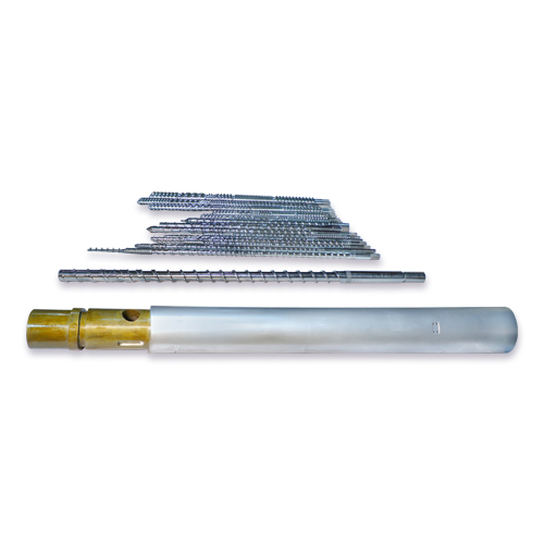
Injection Molding Machine Screw Barrel
Download Brochure
This product page covers the complete Hi-Tech injection molding screw barrel range: material grades, dimensional specifications, machine brand compatibility, heat transfer engineering, drive-end configurations, total cost of ownership, and a detailed product selector table. For application-specific guidance on polymer selection, screw geometry optimisation, and troubleshooting, refer to the companion technical guide.
Price of Injection Molding Screw Barrel
|
Screw Minimum Size (mm or inch) |
Screw Maximum Size (mm or inch) |
Barrel Minimum Size (mm or inch) |
Barrel Maximum Size (mm or inch) |
Minimum Price (In Rs) |
Maximum Price (In Rs) |
|---|---|---|---|---|---|
|
12mm |
250mm |
12mm |
250mm |
Rs. 35,000 |
Rs. 15,00,000 |
Hi-Tech Injection Molding Screw Barrel Complete Product Range
The following table defines the complete Hi-Tech injection molding screw barrel product range, covering all available grades, material specifications, and recommended application categories. Custom configurations beyond this range are manufactured to order.
| Grade / Variant | Screw Material | Barrel Construction | Diameter Range | Recommended Application |
|---|---|---|---|---|
|
Standard Nitrided |
4140 / 42CrMo4 |
40Cr nitrided bore |
18 – 150 mm |
PP, PE, ABS, HIPS, PS – unfilled or lightly filled |
|
Ion Nitrided Premium |
4140 / 42CrMo4 |
42CrMo4 ion nitrided bore |
25 – 180 mm |
High-speed packaging, ABS/PC, colour-critical precision moulding |
|
Bimetallic Standard |
4140 + Stellite tip |
Fe-Cr-C liner (950 HV) |
25 – 200 mm |
GFR compounds 20–35%, CaCO3-filled masterbatch, regrind blends |
|
Bimetallic Premium (Ni-WC) |
1.2344 (H13) + HVOF tip |
Ni-WC liner (1,000+ HV) |
30 – 200 mm |
GFR 35–50%, mineral-filled compounds, continuous 3-shift production |
|
Corrosion-Resistant |
4140 + Cr-plated flights |
Ni-based alloy liner (UNS N10276 equivalent) |
25 – 150 mm |
PVC, PVDC, FR-PA, FR-ABS, brominated flame retardants |
|
High-Temp Engineering (H13) |
1.2344 (H13) tool steel |
42CrMo4 + bimetallic or nitrided |
20 – 120 mm |
PEEK, PPS, LCP, PAI, high-temp PA – processing above 300°C |
|
Vented (Two-Stage) |
4140 or H13 (as above) |
Matched vented barrel with vent port |
30 – 150 mm |
PET, PA6/PA66, PC, POM – moisture-sensitive engineering resins |
|
Micro-Injection |
H13 / 1.2379 precision grade |
Precision-honed bore Ra ≤ 0.1 µm |
14 – 25 mm |
Medical devices, diagnostics, electronics – shot weights 0.01–5 g |
All variants are available with a matched screw tip, check ring, and seat ring assembly. Replacement tip sets are supplied as complete matched sets not individual components – to maintain check ring sealing geometry and shot weight consistency.
Dimensional Tolerances & Manufacturing Standards
The following dimensional parameters are verified at final inspection for every injection molding screw barrel assembly dispatched from Hi-Tech Screw Barrel Works. Tolerances are grade-specific and reflect the manufacturing capability of Hi-Tech’s CNC turning centres, bore honing machines, and metrology instruments.
| Dimension / Parameter | Economy Range | Standard Nitrided | Premium / Bimetallic | Measurement Method |
|---|---|---|---|---|
|
Screw OD Tolerance (on nominal) |
h8 (−0.039 to −0.100 mm) |
h7 (−0.025 to −0.060 mm) |
h6 (−0.013 to −0.040 mm) |
Outside micrometer, 4 positions / 3 planes |
|
Screw OD Concentricity (TIR) |
≤ 0.08 mm |
≤ 0.04 mm |
≤ 0.02 mm |
Dial gauge on CNC centre, full length |
|
Barrel Bore Diameter Tolerance |
H8 (+0.039 to +0.100 mm) |
H7 (+0.025 to +0.060 mm) |
H6 (+0.013 to +0.040 mm) |
Bore gauge, 3 axial / 4 angular positions |
|
Bore Roundness (Cylindricity) |
≤ 0.020 mm |
≤ 0.015 mm |
≤ 0.010 mm |
CMM or V-block + dial gauge |
|
Bore Straightness |
≤ 0.10 mm/m |
≤ 0.07 mm/m |
≤ 0.05 mm/m |
Precision mandrel + indicator |
|
Bore Surface Roughness (Ra) |
0.8 – 1.6 µm |
0.4 – 0.8 µm |
≤ 0.1 – 0.4 µm |
Profilometer, 3 measurements per bore section |
|
Screw Root Runout |
≤ 0.06 mm TIR |
≤ 0.04 mm TIR |
≤ 0.02 mm TIR |
Dial indicator on root diameter |
|
Drive-End Keyway / Spline Fit |
JS9 (±0.026 mm) |
JS8 (±0.018 mm) |
JS7 (±0.012 mm) |
Plug gauges + CMM for spline profiles |
|
Screw Tip Thread (to Screw) |
6H/6g (standard thread) |
5H/6g (close tolerance) |
4H/5g (precision thread) |
Thread ring gauge |
|
Barrel Flange Face Perpendicularity |
≤ 0.06 mm |
≤ 0.04 mm |
≤ 0.03 mm |
CMM flatness measurement |
|
Heater Band Groove Depth Tolerance |
±0.10 mm |
±0.08 mm |
±0.05 mm |
Depth micrometer at 4 positions |
Customers requiring tighter tolerances for specific machine models or applications may specify beyond the premium range Hi-Tech’s CNC infrastructure supports tolerances to IT5 grade on screw OD and H5 bore tolerance on barrel bore for micro-injection and precision all-electric machine applications. Request a dimensional qualification report with your order.
Barrel Heat Transfer Engineering & Heater Zone Configuration
The barrel is not a passive containment vessel it is an active heat transfer component. Barrel heater bands supply the majority of the thermal energy required to melt the polymer; the screw’s mechanical shear adds the balance. The proportion of heat supplied by heater bands versus shear varies significantly by polymer: for low-viscosity polymers such as high-MFI PP, shear heating contributes 10–20% of total energy input; for high-viscosity engineering polymers such as PEEK at 380°C, shear heating may contribute 30–40%. A barrel that cannot maintain precise zone-by-zone temperature under varying production speeds will produce melt temperature inconsistency the single most common root cause of surface defects, dimensional variation, and weld line weakness in moulded parts.
Wall Thickness and Thermal Mass
Barrel wall thickness determines both structural integrity under injection pressure and thermal mass. A barrel wall that is too thin heats and cools rapidly producing fast response but also high sensitivity to production interruptions. A barrel wall that is too thick provides thermal stability during normal production but takes significantly longer to reach set-point temperature at start-up and longer to respond to zone temperature corrections. Hi-Tech designs barrel wall thickness at 20–30% of bore diameter for standard injection moulding applications – a ratio established through field experience across a wide range of machine sizes and polymer types to balance thermal responsiveness with structural rigidity.
Heater Band Groove Geometry
Heater bands seat in precision-machined grooves on the barrel OD. The groove depth, width, and surface finish determine the contact quality between the heater band and barrel surface poor contact creates hot spots and local overheating that accelerates barrel bore oxidation and polymer degradation. Hi-Tech machines heater grooves to ±0.05 mm depth tolerance on premium barrels, ensuring full 360° contact between band and groove. Groove surface finish Ra ≤ 1.6 µm is maintained to prevent contact-point air gaps. Customers specifying a replacement barrel for an existing machine must provide the heater band OD, width, and groove-to-groove pitch – these are confirmed against the machine specification before machining begins.
Feed Throat Water Cooling
The feed throat section of the barrel immediately below the hopper opening must be maintained at 40–80°C regardless of the processing temperature of the polymer zones downstream. This cooling prevents premature melting and bridging of polymer pellets in the feed throat, which causes the irregular solid plug conveying that appears as output surging and screw RPM oscillation. Hi-Tech supplies barrels with feed throat water cooling grooves as standard on all assemblies above 60 mm diameter, and on request for smaller diameters. The cooling groove design a precision-machined helical channel sealed with a fitted plug ensures uniform temperature across the full feed throat circumference.
Barrel Material Thermal Conductivity
Alloy steels used for injection moulding barrels 40Cr, 42CrMo4 – have thermal conductivity values of approximately 42–46 W/(m·K). This is substantially lower than copper (385 W/(m·K)) but appropriate for the controlled heat-transfer application: too high a conductivity would make zone-by-zone temperature control impossible, as heat would conduct freely along the barrel length. The bimetallic alloy liner (Fe-Cr-C or Ni-WC) has slightly lower conductivity (28–35 W/(m·K)) than the outer barrel steel – this minor reduction has negligible impact on heating zone performance in practice, as the liner represents only 1.5–3.0 mm of the total 15–40 mm barrel wall thickness.
Screw Root Strength & Torque Capacity Engineering
The screw root – the solid cylindrical core running the full length of the screw inside the helical flight is the most structurally critical section of the injection molding screw barrel assembly. During the plasticating stroke, the screw root must transmit the full motor torque from the drive end to the flight surfaces along the entire active screw length. During the injection stroke, it must resist the full compressive axial load as the screw advances against 1,000–2,500 bar melt pressure. A screw root that is under-dimensioned for either of these loads will fail – sometimes catastrophically at cold start-up, where polymer frozen between the flights imposes maximum torque demand simultaneously with the rigidity of the cold barrel bore.
Root Diameter Profile and Compression Ratio Relationship
The root diameter determines both the screw’s torsional stiffness and the channel depth profile that creates the compression ratio. A screw with a high compression ratio has a rapidly increasing root diameter from feed to metering zones creating the shallowest possible channel at the metering end. This geometry maximises shear energy and compression efficiency but minimises the material cross-section in the transition zone, where torsional fatigue cracks most commonly initiate. Hi-Tech’s screw design specifies a minimum root diameter at each zone transition based on a torsional stress analysis for the maximum rated machine torque – not the nominal torque – ensuring the screw survives the highest-demand cold-start scenario without plastic deformation or fatigue crack initiation.
Root Radius at Zone Transitions
The geometric stress concentration at zone transitions where the root diameter steps from the shallow feed channel depth to the shallower metering depth is the primary initiation site for torsional fatigue cracks on injection moulding screws. Sharp internal corners at these transitions act as stress risers that can multiply the nominal torsional stress by a factor of 2–4. Hi-Tech machines all zone transition radii to a minimum of R3 mm on screws below 80 mm diameter and R5 mm on larger diameters. On H13 premium screws, transition radii are increased to R5–R8 mm and the surface is polished to Ra ≤ 0.4 µm to eliminate micro-crack nucleation sites at the critical transition zone.
Drive-End Configurations - Key, Spline, and Polygon
The drive end of the injection moulding screw transmits torque from the machine gearbox or servo motor to the screw body. Three principal drive configurations are used across the range of injection moulding machines in the Indian market:
• Parallel Key Drive: The most common configuration on hydraulic injection moulding machines. A single or double parallel key sits in a machined keyway. Hi-Tech machines keyways to DIN 6885 standard with a JS7 or JS8 tolerance on keyway width for tight, backlash-free key fit. The key contact face is hardened to prevent brinelling under repeated injection shock loading.
• Involute Spline Drive: Used on higher-torque hydraulic machines and many electric machines where torque is too high for a single parallel key. Hi-Tech produces splines to DIN 5480 or ANSI B92.1 standards, depending on machine specification. Spline profile accuracy is verified with CMM measurement of each spline tooth profile.
• Polygon (Polygonal) Drive: Used on several European and Japanese electric injection machine brands where zero-backlash torque transmission is required for precision moulding. The polygon profile – typically a P3G or P4C form to DIN 32711 – is machined and verified to the machine-specific dimensional standard.
When ordering a replacement screw, the drive-end configuration and all relevant dimensions – key size and tolerance, spline module and tooth count, polygon designation must be confirmed. An incorrectly specified drive end cannot be corrected without full re-manufacture of the screw shank.
Wear Pair Engineering - Why Matched Hardness Matters
The injection molding screw barrel is an inherently tribological system two steel surfaces in relative motion, separated by the polymer melt, with abrasive filler particles acting as a third-body abrasive medium in filled-compound applications. Understanding the wear pair physics is essential to specifying an assembly that wears at a controlled, predictable rate rather than failing unexpectedly.
The Hardness Delta Rule
In any two-body wear system, the softer surface wears preferentially. In the injection molding screw barrel, the screw flight OD and barrel bore ID are the primary wear pair. The hardness difference between these two surfaces the hardness delta determines the wear rate distribution between them. The optimal specification is a controlled hardness delta of 50–100 HV in favour of the barrel bore: the bore should be slightly harder than the screw flight OD. This controlled delta ensures that any wear occurs preferentially on the screw flight (the lower-cost, more easily replaced component in a matched assembly) rather than on the barrel bore, while preventing the catastrophic seizure risk that occurs when the two surfaces approach equal hardness and galling becomes possible.
In practice: a standard nitrided barrel at 750 HV paired with a standard nitrided screw at 900 HV on flights violates this rule the screw flights are 150 HV harder than the bore. Any abrasive particle caught between them preferentially abrades the bore. Hi-Tech matches hardness specifications deliberately: standard nitrided assemblies are specified with bore hardness 800–850 HV and screw flight hardness 750–800 HV, maintaining the correct delta. Bimetallic assemblies use bore hardness 950–1,000 HV against screw flight hardness 900–950 HV, maintaining the same delta at a higher absolute hardness level for filled-compound service.
Third-Body Abrasion and Filler Particle Size
Filler particles calcium carbonate, glass fibre, talc, titanium dioxide act as abrasives when their hardness exceeds that of the screw or barrel surface. Calcium carbonate (calcite) has a Mohs hardness of 3.0 (approximately 110 HV Vickers), which is significantly softer than a nitrided surface at 750+ HV – CaCO3 on its own causes minimal wear on a correctly specified nitrided assembly. Glass fibre, however, has a Mohs hardness of 6.5–7.0 (approximately 730–820 HV Vickers) directly overlapping with the surface hardness of standard nitrided assemblies. This is why standard nitrided components fail rapidly in GFR compound service: the glass fibre particles are essentially the same hardness as the nitrided surface, producing three-body abrasive wear rather than the low-wear sliding contact that occurs when filler hardness is well below surface hardness. A bimetallic bore at 950–1,000 HV is significantly harder than glass fibre, reducing GFR wear rate by 3–5 times versus standard nitrided.
Corrosive Wear Mechanism in PVC and FR Compounds
Corrosive wear in injection moulding screw barrels differs fundamentally from abrasive wear. HCl gas released during PVC processing attacks the iron matrix of nitrided steel, dissolving the iron oxide passivation layer and exposing fresh metal to further attack. The corrosion product iron chloride is itself softer and more susceptible to removal by mechanical action than the original steel surface, creating a self-accelerating degradation cycle. Corrosion-resistant alloy liners (Ni-based, Hastelloy-equivalent) resist this cycle by presenting an alloy surface whose passive film is resistant to Cl⁻ ion attack. The critical specification parameter is not just liner hardness but liner alloy composition a liner with insufficient nickel or molybdenum content will corrode progressively despite its hardness. Hi-Tech’s corrosion-resistant barrel liners are specified to a minimum nickel content of 55% and minimum molybdenum content of 16% to match the corrosion resistance class required for continuous PVC and FR compound service.
Purge Efficiency & Colour Changeover Productivity
One of the most practically significant yet least publicised performance differences between a correctly specified injection molding screw barrel and a worn or poorly specified assembly is purge efficiency. In colour-intensive moulding operations, the time spent purging between colour changes directly impacts machine utilisation and profitability. A machine running 8 colour changes per shift, each requiring an additional 15 minutes of purge time due to a rough bore surface or worn screw creating dead zones, loses 2 hours of productive moulding time per shift – equivalent to 25% of the shift’s output.
How Bore Surface Finish Affects Purge Time
The mechanism is straightforward: polymer adheres to rough bore surfaces in proportion to the surface energy and contact area of the roughness features. A bore with Ra 1.6 µm has approximately 4 times the true contact surface area of a bore with Ra 0.4 µm of the same nominal diameter and proportionally greater adhesion and retention of the preceding colour. The retained colour then bleeds into the subsequent shot over 20–60 cycles rather than being displaced by the first purge shot. Hi-Tech’s premium bore finish (Ra ≤ 0.2 µm on polished variants) eliminates this adhesion mechanism, reducing colour changeover purge volume by 30–60% compared to standard-finish assemblies in PP and ABS colour-critical applications. This improvement is measurable in the moulding facility and directly converts into recoverable production capacity.
Check Ring Dead Volume and Stagnation
The screw tip and check ring assembly creates a small dead volume between the check ring rear face and the screw nose a region where melt velocity approaches zero during the injection stroke. In this dead zone, polymer experiences extended residence time at melt temperature, progressively degrading and forming carbon deposits that resist displacement during normal purging. Hi-Tech designs the check ring geometry to minimise this dead volume: the angle between the check ring rear face and the screw nose is machined to ≤ 10° to ensure self-cleaning flow during the plasticating stroke, and the internal flow channel through the screw tip is streamlined to eliminate recirculation zones. These geometry details are specified on Hi-Tech’s premium tip assembly sets and are not present on generic replacement check ring assemblies.
Quantified Purge Productivity Improvement
Based on field experience across multiple Hi-Tech customer installations in India’s consumer goods packaging and appliance sectors, replacing a worn standard-finish assembly (bore Ra 0.8–1.2 µm) with a Hi-Tech premium assembly (bore Ra 0.2–0.4 µm) and matched tip set produces the following measurable improvements: colour changeover purge volume reduction of 35–55% for standard PP and ABS colour changes; black speck clearance purge time reduction of 40–60% after startup from cold; and machine utilisation improvement of 8–15% on high-colour-change-frequency lines (6+ changes per shift). [Field data – confirm specific figures from Hi-Tech’s installation records before publishing].
Quality Documentation & Inspection Certification
Every injection molding screw barrel assembly dispatched from Hi-Tech Screw Barrel Works is accompanied by a standard inspection certificate covering the following parameters. Additional documentation is available on request for medical, food contact, and export applications.
| Document | Screw Material | Availability |
|---|---|---|
|
Dimensional Inspection Report |
Screw OD, concentricity, root runout; bore ID, roundness, straightness; flange dimensions; drive-end fit |
Standard – included with every order |
|
Hardness Test Report |
Screw flight HRC at 3 positions; bore HV (Vickers) at 3 axial positions; core hardness verification |
Standard – included with every order |
|
Surface Roughness Certificate |
Bore Ra (µm) at 3 positions; screw flight Ra at tip and root |
Standard – included with every order |
|
Material Test Certificate (MTC) |
Steel grade, heat number, chemical composition, UTS, yield strength, elongation as per EN 10204 3.1 |
On request – add at time of order |
|
Nitriding / Heat Treatment Record |
Process type (gas / ion), temperature, duration, nitrogen potential, white layer measurement (ion nitriding) |
On request – add at time of order |
|
Bimetallic Liner Certificate |
Alloy composition, casting batch number, liner thickness at 4 positions, bond integrity confirmation |
Standard on all bimetallic orders |
|
FAT (Factory Acceptance Test) Report |
Full 12-point inspection against customer drawing – signed and stamped by Hi-Tech QC |
On request – for OEM and batch supply orders |
Benefits
Precision Melt Control and Mixing
Injection molding screw barrels ensure precise melt control and thorough mixing of additives, colorants, and fillers into the polymer melt. This results in uniform melt quality and enhanced part aesthetics.
Extended Service Life and Durability
Our screw barrels are manufactured from high-quality materials, including nitrided steel, bimetallic alloys, and tungsten carbide coatings, to withstand abrasive wear and corrosion. This ensures extended service life and reduced maintenance downtime.
Optimized Injection Molding Parameters
By optimizing screw design and material selection, our screw barrels enhance injection molding parameters such as cycle time, shot size consistency, and part dimensional stability. This improves overall production efficiency and reduces scrap rates.
Customization Options
We offer customization options to meet specific customer requirements, including screw diameter, length-to-diameter ratio (L/D), flight geometry, material composition, and surface treatments. Our engineering expertise ensures that each injection molding screw barrel is optimized for maximum performance and reliability.
FAQs
What is the function of a screw barrel in an injection molding machine?
The screw barrel is a crucial component responsible for plasticizing, mixing, and injecting molten plastic into the mold cavity. The screw rotates inside the barrel, conveying plastic material while applying heat and pressure to ensure uniform melting and consistency in the final molded product.
What materials and grades are used to manufacture injection molding screw barrels - and how do I choose the right one?
Injection molding screw barrels are manufactured in three primary material grades, each suited to different service conditions:
Nitrided steel – the standard grade for general-purpose applications processing commodity resins (PP, ABS, HIPS, PE). Ion nitriding (plasma nitriding) produces a white-layer-free diffusion zone that is tougher and more fatigue-resistant than conventional gas nitriding. Hi-Tech’s standard assemblies are ion nitrided to a case depth and hardness that consistently outperforms gas-nitrided import-grade equivalents.
Bimetallic barrel with standard screw – the recommended configuration for abrasive applications (glass-filled, mineral-filled, or recycled compounds) and for machines running above 80% utilization. The barrel bore is lined with a centrifugally cast bimetallic alloy (Xaloy 306 equivalent or superior) that provides hardness typically in the 60–65 HRC range at the bore surface. This extends barrel life by 3–5× compared to nitrided-only barrels in filled-compound service. The screw flights can be paired with HVOF-coated or hardface-welded tips for complete abrasion protection.
H13 / corrosion-resistant alloy – specified for engineering polymers processed above 280°C (LCP, PEEK, PPS), PVC, and flame-retardant compounds where corrosive off-gases attack standard nitrided surfaces. Corrosion-resistant bimetallic grades (Colmonoy 56 equivalent) are available for PVC and FR compound service.
When specifying material grade, provide the polymer, filler type and loading, melt temperature, and average shot weight – Hi-Tech will confirm the appropriate grade.
What factors determine the design of an injection molding screw barrel - and how does design affect machine efficiency?
Screw barrel design is determined by five interdependent factors: polymer type and rheology, required melt temperature, injection pressure, barrel length-to-diameter (L/D) ratio, and application type (thin-wall, medical, packaging, technical moulding).
The key design parameters and their effect on performance:
Screw diameter sets the shot capacity range. Undersized diameter relative to shot weight forces the screw to operate at low fill levels, producing inconsistent melt quality. Oversized diameter means long residence times and thermal degradation risk for heat-sensitive resins.
Compression ratio controls the pressure applied during melting. Higher compression ratios (3.5:1–4.5:1) suit amorphous resins like ABS and PC; lower ratios (2.5:1–3.0:1) suit semi-crystalline resins like PP and PA that have a sharp melting point.
L/D ratio governs residence time and plasticizing capacity. Standard injection moulding screws run 20:1–22:1 L/D. Higher L/D (24:1–26:1) is used where additional homogenization or mixing is required – for example, masterbatch-intensive or filled-compound applications.
Mixing section geometry – distributive mixing elements (pineapple, Maddock, diamond) are added for colour consistency and filler dispersion. Specifying the wrong mixing section for the application is a common source of black specks, colour streaks, and shot weight variation.
Screw flight clearance affects sealing, leakage, and energy efficiency. Tight clearance improves melt pressure consistency but demands tighter concentricity specification, particularly on all-electric machines (see Q5).
Hi-Tech designs screws to the specific combination of machine platform, polymer, and production requirement – not to a generic standard geometry.
How long does an injection molding screw barrel last - and what are the signs it needs replacement or reconditioning?
Service life depends on material grade, polymer and filler abrasiveness, processing temperature, and maintenance discipline. Indicative service life benchmarks:
• Standard nitrided, commodity resins (PP/ABS/PE), normal utilization: 18–30 months
• Bimetallic barrel, glass-filled or mineral-filled compounds (20–40% loading): 24–48 months
• Standard nitrided running abrasive compounds (glass-filled, recycled, FR): 6–12 months – bimetallic upgrade is strongly recommended in this case
Signs that inspection, reconditioning, or replacement is needed:
• Shot weight scatter increasing beyond ±0.5% of target – first indicator of check ring or bore wear
• Inconsistent melt flow or surging during injection
• Increased plasticizing cycle time without process changes
• Visible wear on screw flights (land wear measurable by flight clearance gauge)
• Black specks or colour streaks that persist after purging – often indicates dead zones from a scored bore or worn mixing section
• Frequent short shots or flash on the same part geometry – indicates shot volume inconsistency from check ring bypass
To extend service life:
• Match the material grade to the polymer and filler loading – the single most effective measure
• Maintain correct temperature profiles; barrel overheating accelerates wear and thermal degradation
• Use purging compound during material changes and shutdowns
• Schedule bore measurement (air gauge or plug gauge) at regular intervals to track wear rate before it becomes a production problem
If multiple signs appear together, reconditioning (re-nitriding and flight hard-facing) may restore an assembly to near-original specification at 40–60% of replacement cost. Hi-Tech can advise on reconditioning eligibility after inspection.
Can one injection molding screw barrel handle multiple plastic materials?
While a general-purpose screw barrel can process a range of commodity resins, performance is always optimized when the screw geometry and barrel grade are matched to the primary polymer. Key considerations:
• Barrier screws provide superior melting and homogenization for high-viscosity or semi-crystalline polymers (PA, POM, PBT) and reduce cycle time by improving melt quality at lower temperatures
• Vented (two-stage) screws are essential for moisture-sensitive resins (PA, PC, PET) processed without pre-drying, and for recycled or regrind-heavy material streams where volatiles must be evacuated
• Mixing-section screws are specified where consistent colour dispersion or filler distribution is critical
When switching between materially different polymers on the same machine – for example, from PP to PVC – the screw barrel grade must also be compatible with the corrosive off-gases produced by PVC. Running PVC on a standard nitrided assembly accelerates bore corrosion. Always confirm grade compatibility when the polymer family changes.
How do I order a replacement injection molding screw barrel from Hi-Tech - and how is compatibility verified before manufacture?
Information required when ordering:
To confirm dimensional compatibility before manufacture, provide:
1. Machine brand and model number (as shown on the machine nameplate)
2. Nominal screw diameter – measure with an outside micrometer on the unworn section of the existing screw if possible
3. L/D ratio – measure total screw working length and divide by nominal diameter
4. Drive-end configuration – parallel key (provide key size and keyway dimensions), spline (DIN/ANSI standard and module), or polygon (provide polygon designation)
5. Surface treatment of the existing assembly – nitrided or bimetallic
6. Polymer being processed, including filler type and percentage loading
7. Any known performance issues (shot weight scatter, black specks, short service life) – this helps Hi-Tech specify a grade upgrade if the current specification is contributing to the problem
If OEM drawings are available, scan and supply them – they eliminate dimensional ambiguity and reduce the risk of incompatibility discovered only at installation.
Hi-Tech’s compatibility verification process:
Once an enquiry is received, Hi-Tech follows a four-step verification protocol:
Step 1 – Drawing review: If an OEM drawing or previous Hi-Tech inspection certificate is available, the specification is confirmed against published machine manufacturer dimensional standards. Any discrepancy is flagged before manufacture begins.
Step 2 – Cross-reference check: For major machine brands in Hi-Tech’s database, the screw diameter and machine model are cross-referenced against Hi-Tech’s OEM compatibility records to confirm drive-end configuration, flange bolt circle, and heater groove layout.
Step 3 – Reverse-engineering from worn sample: If no drawing is available, ship the worn screw and/or barrel to Hi-Tech’s Ahmedabad facility. The metrology team measures all critical dimensions on CNC CMM equipment and produces a dimensional report for customer approval before machining begins. This service is included in the assembly price – no separate engineering charge for standard reverse-engineering.
Step 4 – First-off inspection on batch orders: For OEM supply batches, the first manufactured assembly is presented with a full factory acceptance test (FAT) inspection report for customer approval before the remaining batch is produced.
This process eliminates the costly scenario of discovering a dimensional incompatibility on a machine that has already been waiting for its replacement assembly.
What are the lead times for injection molding screw barrels from Hi-Tech, and do you hold stock?
Lead times depend on whether the assembly falls within Hi-Tech’s standard catalogue range:
Standard catalogue assemblies: maintained as semi-finished blanks, enabling finished manufacture and dispatch within 7–12 working days from confirmed order.
Bimetallic barrels not in blank stock: require an additional 5–7 working days for the centrifugal casting and bonding process.
Custom and non-catalogue assemblies (non-standard diameters, special thread forms, vented designs, H13 high-temperature grade, micro-injection assemblies): 15–25 working days from technical confirmation.
Breakdown/emergency orders: For standard-catalogue assemblies, priority processing within 5 working days is available in some cases – discuss urgency and machine downtime situation with the Hi-Tech sales team at time of enquiry.
Dispatch is by road freight to all major Indian cities; air freight is available for urgent requirements. There is no minimum order quantity – Hi-Tech supplies single-piece replacement assemblies and volume OEM batches at the same quality standard.
Can Hi-Tech supply injection molding screw barrels for all-electric machines - are the tolerances different?
Yes. Hi-Tech supplies replacement screw barrel assemblies for all-electric and hybrid injection moulding machines.
All-electric machines impose three specification requirements that differ from hydraulic machine standards:
Tighter concentricity: High screw speeds (250–300 RPM) on electric machines amplify the effect of any eccentricity in the screw OD, generating cyclic bore loading that accelerates wear and produces melt temperature differentials across the bore cross-section. Hi-Tech’s premium concentricity specification of ≤ 0.02 mm TIR is the appropriate standard for all-electric machines. The standard ≤ 0.05 mm tolerance used for slower hydraulic machines is not adequate.
Tighter drive-end fit: Electric servo drives with zero-backlash requirements need spline or polygon drive interfaces machined to tighter tolerances than parallel key hydraulic drives. Hi-Tech’s CMM-verified spline and polygon profiles meet this requirement.
Dynamic balance: At screw speeds above 200 RPM, dynamic balance of the screw assembly becomes relevant. Hi-Tech can supply balance certification for screws intended for high-speed electric machine applications on request.
When ordering for an all-electric machine, specify the machine model and nominal screw speed so Hi-Tech can confirm the appropriate concentricity and drive-end specification.
Does Hi-Tech supply screw tip and check ring assemblies separately from the screw barrel?
Yes. Hi-Tech supplies screw tip assemblies (screw tip nose, check ring, and seat ring) both as part of a complete screw barrel assembly and as standalone replacement sets.
When supplied as standalone replacements, the tip, check ring, and seat ring are manufactured and matched as a complete set – not as individual items. This is a critical distinction: the sealing performance of the check ring depends on the geometric relationship between the check ring face, the seat ring face, and the travel clearance within the check ring bore. Replacing only one component – for example, a worn check ring while retaining the original seat ring – perpetuates shot weight variation because the new component’s geometry has not been matched to the worn mating face.
Hi-Tech’s matched tip sets are available in:
• Standard alloy steel – for PP, ABS, PE service
• H13 – for engineering polymers processed above 280°C
• Corrosion-resistant alloy – for PVC and FR compound service
When ordering a standalone tip set, specify the screw diameter, thread pitch at the screw nose, and polymer application.
What warranty and performance guarantee does Hi-Tech provide on injection molding screw barrels?
Hi-Tech Screw Barrel Works provides a dimensional compliance guarantee on all injection molding screw barrel assemblies: every dispatched assembly meets the dimensional and hardness specifications stated on the inspection certificate, and any assembly that fails to conform to these documented specifications will be replaced or credited without charge.
For service life, Hi-Tech provides application-specific guidance – a screw barrel specified for the correct polymer, filler loading, and service condition will deliver the typical service life published for that grade (for example, 24–36 months for bimetallic grade in glass-filled PA66 service). Premature wear resulting from process conditions outside the original specification – such as running a standard nitrided assembly on 40% glass-filled compound, or processing PVC on a nitrided barrel – is not covered, as these conditions exceed the design envelope of the specified grade.
For new applications where field service life data is not yet available, Hi-Tech recommends an initial bore inspection at 6 months to establish a wear rate baseline before predicting the replacement interval.
Do you provide installation support and maintenance services for injection molding screw barrels?
Yes. We offer complete installation guidance, technical support, and maintenance services for screw barrels. Our team can assist with proper alignment, troubleshooting, and reconditioning to maximize machine performance and extend the lifespan of the screw barrel.
Why Choose Us?
")
Expertise and Experience
With over 22 years of industry experience, we are leaders in the manufacturing of single screws, backed by a team of skilled professionals.

Advanced Manufacturing Facilities
Our state-of-the-art production facility is equipped with cutting-edge technology and CNC machines, ensuring precision and consistency in every component we manufacture.

Commitment to Quality
We adhere to stringent quality control standards throughout the manufacturing process, ensuring that each single screw meets our high-quality standards and exceeds customer expectations.

Customer-Centric Approach
We prioritize customer satisfaction and strive to provide personalized solutions and exceptional service. Our dedicated team is ready to assist you with technical expertise and support.